
-
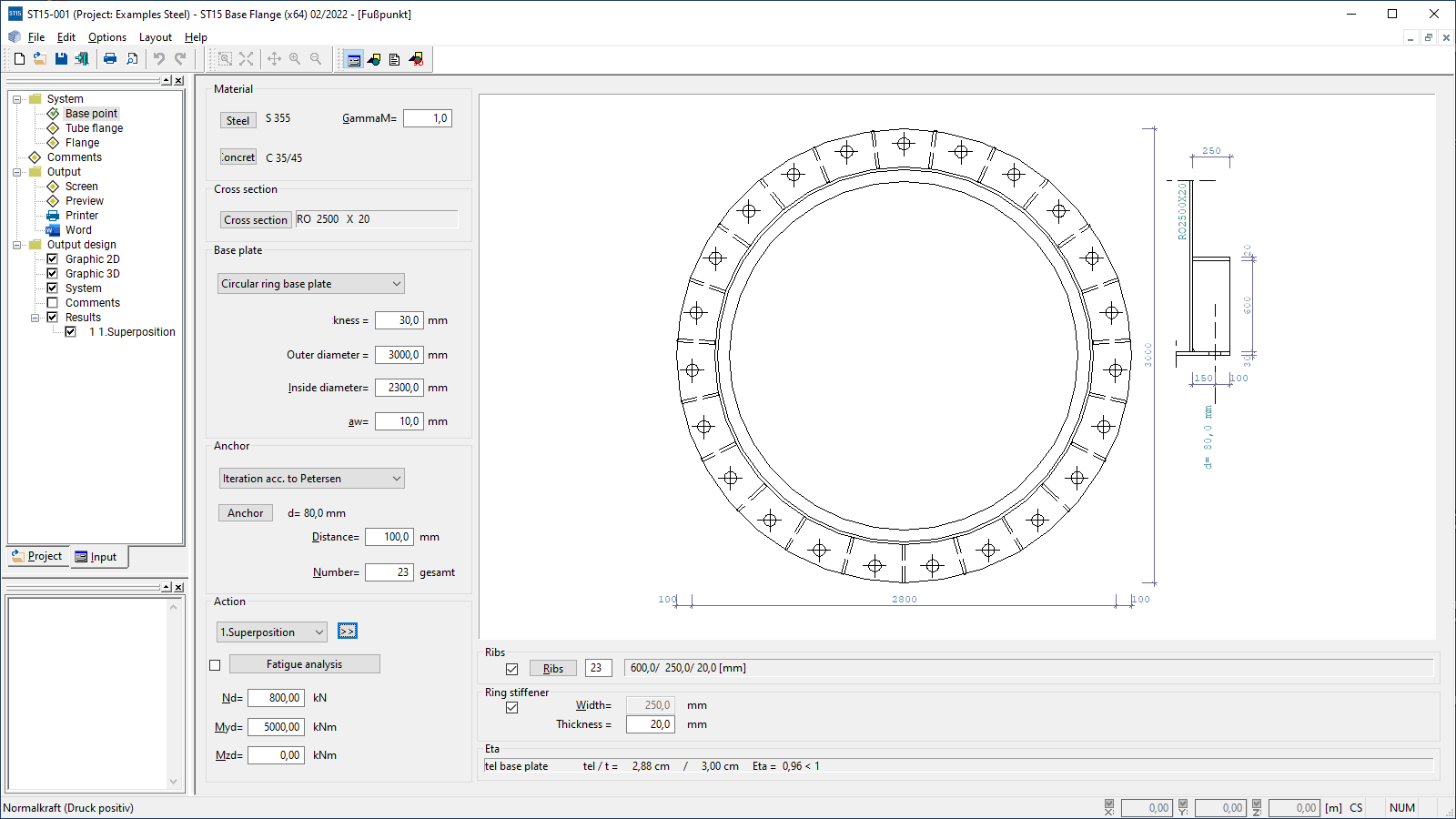 ST15 user interface
 -
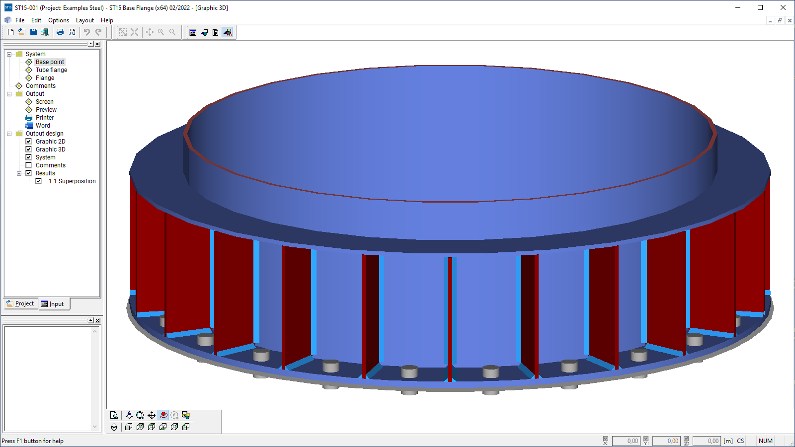 Graphical representation in 3-d
 -
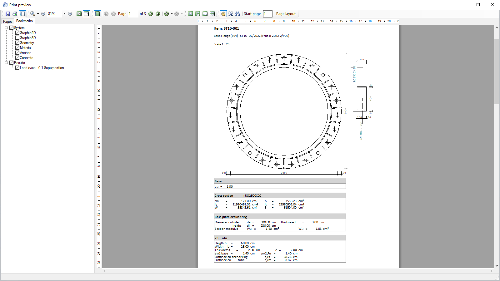 Output document
Base Flange
ST15
The ST15 program is used to calculate pipe flange connections and bases of annular components as well as single flange connections.
Discover now more programs from the section Steel!
SHOW MOREMaterial
- Structural steel: S235, S275, S355,
- Annealed steel (S275N, S355N)
- General structural steel (St 37-2, St37-3, St52-3)
- Stainless steel (1.4301 to 1.4561)
- High-temperature steel (H II, 1.0425, 15 Mo3,1.5415)
- User-defined steel
For the base in addition:
- Reinforced concrete C12/15 to C50/60
- Reinforced concrete B10 to B35
Structural system
System:
- Base (circular, rectangular, annular base plate)
- Pipe flange
- Flange (inside or outside)
Cross-sections:
- Base:
- Circular pipes as standard sections
- User-defined circular hollow sections
- Pipe flange:
- Circular pipes as standard sections
- User-defined circular hollow sections
- Flange:
- User-defined cross-sections
Loads
Pipe flange:
- Design internal forces from axial force and moment
- Multiple combinations of internal forces can be entered
Base
- Design internal forces from axial force and moment
- Multiple combinations of internal forces can be entered
Flange:
- Entry of a tensile force or the stress in the tie member
Fasteners
Base:
- Screws M12; M16; M20; M22; M24; M27; M30; M36; strength classes 4.6; 5.6; 8.8; 10.9
- Tee-head bolts M24-M64, M72x6, M80x6, M90x6, M100x6; strength class 3.6
- Free entry of anchors
Pipe flange:
- Screws M12; M16; M20; M22; M24; M27; M30; M36; strength classes 4.6; 5.6; 8.8; 10.9
Flange:
- Screws M12; M16; M20; M22; M24; M27; M30; M36; strength classes 4.6; 5.6; 8.8; 10.9
General
The design of flange connections is performed following Petersen Stahlbau, 2nd edition, p. 506 et seq. and p. 952 et seq.
The calculation is based on the analysis of the maximum tensile stress on the pipe and/or the tension plate.
Service strength verification as per DIN 4133
If the service strength verification is performed, the stress calculated from the effects of actions is considered as alternating stress and compared to the permissible values for the service strength: max Δσ ≤ ΔσR
The user can pre-set these values as a reference for the service strength ΔσA of the construction detail in accordance with the notch class as per table 1 of DIN 4133 for the screws, the reinforcing steel, the base, the flange, the webs, the pipe and the annular stiffener.
The factor n for the calculation of the service strength ΔσR is determined by the alternating stress values and the boundary conditions as per DIN 4133, Annex B, Item 3 and must be specified.
ΔσR=ΔσA × n as per eq. (B.3) DIN 4133
For plate thicknesses t > 25 mm, ΔσR can be reduced in accordance with eq. (B.4) in DIN 4133.
Flange design
The flange design is based on Petersen Stahlbau, 2nd edition, p. 953 et seq., “Laschenstöße – Flanschstöße”, or p. 506 et seq., “Stirnplatten und Flanschverbindungen”.
Document file formats
- Word
- Printer
Output
- User-defined
Export options
- DXF-file
Steel construction
- DIN 4133
News
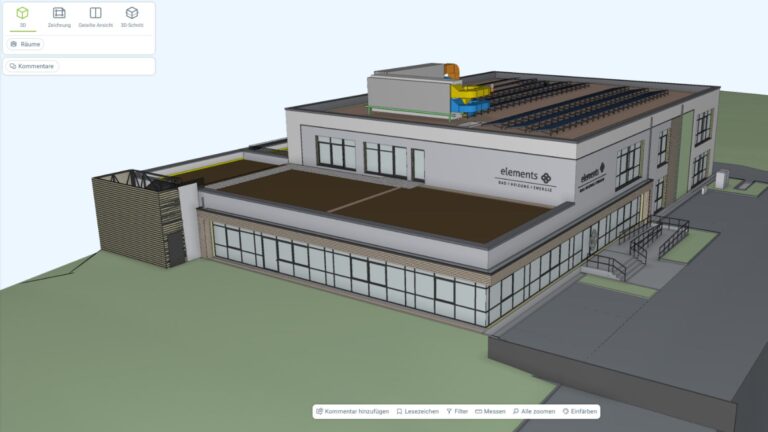
Role model baues + partner – Multi-layered and progressive BIM planning
BIM is not software, but a planning method: this is demonstrated by the ultra-modern multifunctional building that will be built on the Gottschall + Sohn KG company premises.

“FRILO means precise and efficient work to me”
By switching to the FRILO Suite, the engineering office BILGER INGENIEURE decided to rely on the FRILO subscription model. The numerous advantages convinced the long-standing customer.