Material-independent calculation of continuous beams
The FRILO program Continuous Beam can be used to calculate single-span beams and continuous beams of reinforced concrete, steel and timber with any number of spans and with or without cantilevers. In the framework of Release 2023-1, the most widely used FRILO program has now been transferred to the modern and user-friendly PLUS version. The unique selling point of DLT+ is also retained in the new program version: the user can switch interactively between the three types of materials.
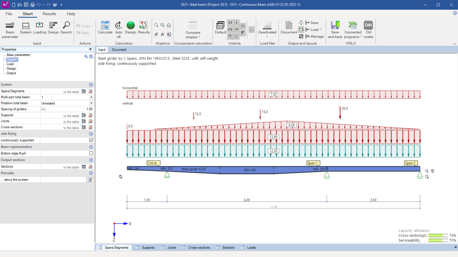
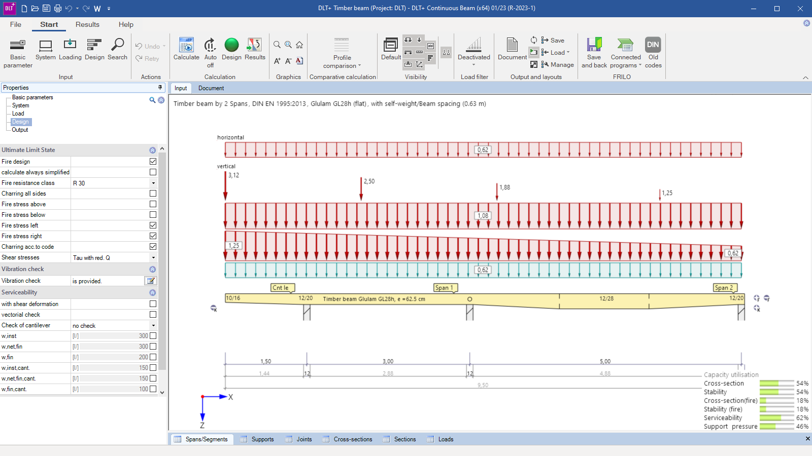
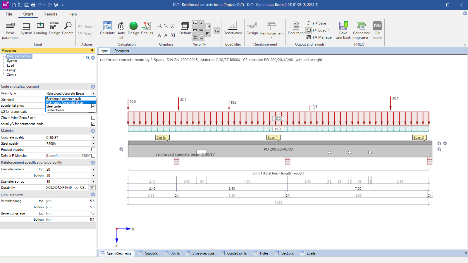
The program Continuous Beam DLT+ can be used to calculate single-span or multi-span beams with any number of spans. Pure cantilever beams can also be defined. The cross-section can be designed variably, either with a haunch, as a multi-part cross-section or with joints. Already when launching the program, the wizard prompts the user to choose between a timber beam, a steel beam, a reinforced concrete beam or a reinforced concrete slab. If the material needs to be changed at a later point in time, this can be done interactively in the item – even after all geometries and loads have been entered. If no suitable cross-section for a timber beam is found during the calculation, for instance, the user can simply switch to another material. All settings concerning the structural system, the loads and the output document are kept unchanged. This allows a material-independent calculation that makes it much easier for structural engineers to deal with complex challenges in their daily work.
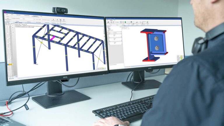
The interactive graphical user interface (GUI)
The data are entered either in tables or in the completely interactive GUI. In the latter case, the user can adjust the selected dimensions of the structural system directly in the GUI via adaptive dimensional chains. Also loads can be added, deleted, moved or edited already in the GUI. This allows a quick adjustment of the beam directly in the graphical representation of the structural system.
Special data-entry options for each material
Regardless of the selected material, the layout of the user interface and the data entry are uniform in the DLT+ program. That is why users immediately become familiar with it and can work intuitively and efficiently. Additional special data-entry options are available for each of the three types of material. For structural systems made of reinforced concrete, tee beams with variable slab positions can be defined in addition to classic rectangular beams. Non-standard steel beams can be defined as general cross-sections by entering user-defined structural values and can be saved for later use. The user can apply additional lateral reinforcement to timber beams by timber or steel cross-sections.
Reinforcement layout
A special feature is the completely revised, interactive and intuitive control of the reinforcement layout. Individually designed reinforcement graphics can be generated for uniform rectangular cross-sections, tee beams and slabs. In this process, the user can also consider recesses and reinforce them. The program suggests users a reasonable reinforcement based on the defined settings, which can be adjusted according to their own requirements. Reinforcement bars – and thus the reinforcement values – can be configured individually and put out in the form of a reinforcement graphic.
Calculation
The calculation is always based on the standard set in the Continuous Beam program DLT+ and the associated safety concept. Depending on the selected material, additional verifications are also available. When designing systems made of reinforced concrete, a wide range of special provisions can be made according to the standard and the verification of deflection in state II can be performed. For a reinforced concrete beam defined as a tee beam, several different construction joints are now available for the structural system. This allows the definition and calculation of more complex beams with different joint formations. Beams made of steel and timber can optionally also be calculated for their resistance to biaxial loads and for their stability. In timber construction, in addition to a fully automatic hot design, users can also perform a vibration analysis according to the verification workflow specified in DIN EN 1995 or according to Winter/Hamm/Richter, 2010.

