
Cross Section Stress Analysis
The “Cross Section Stress Analysis” program can be used to enter cross-sections in graphic and numerical mode, calculate their properties and display them. Tensile stress can be excluded in the determination of the cross-sectional properties. Drawing aids such as polygon lines, circles, rectangles etc. are available for the graphical definition of the cross-section outline.
Only available in FRILO Professional und FRILO Ultimate
Core capabilities
Structural system
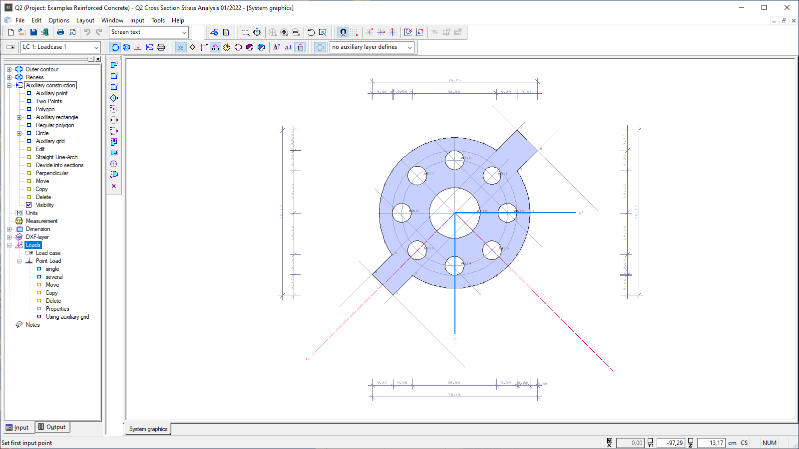
The program offers a graphical user interface, i.e. elements such as outlines, block-outs, load coordinates etc. can be drawn on the screen using the mouse. Under normal conditions, the user must enter only the values of forces etc. numerically in the corresponding dialogs. The available data-entry functions are rectangles, polygon lines, circles and arches. In addition, all elements can be edited using functions like mirror, rotate, or displace. Properties and coordinates can also be entered at any time with their exact values via numeric data-entry fields. Moreover, auxiliary lines and DXF-slides are available to facilitate data entry.
Loads
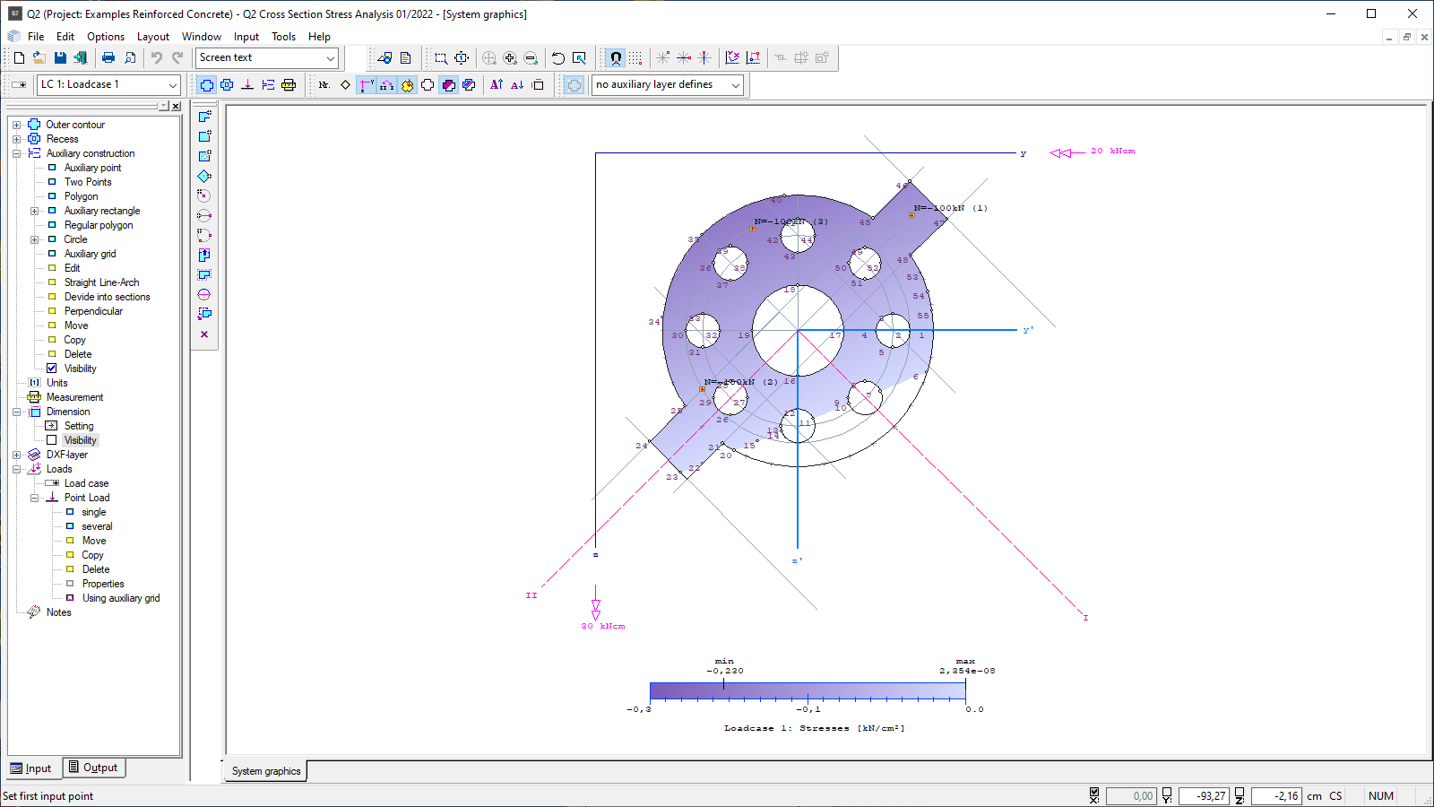
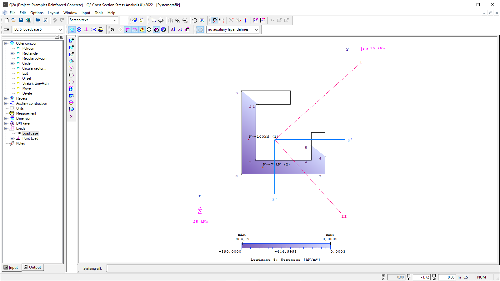
The loads acting on the cross-section can be entered by specifying moments about the horizontal and vertical axes (My, Mz) in a table. In addition, the axial forces can be graphically positioned on the cross-section. The data are entered via specifically defined load cases that can be created by the user.
Cross-sectional properties
- Cross-sectional area (A)
- Location of the centre of gravity (ys/ zs)
- Static moments (Sy, Sz)
- Area moments of inertia (Iy, Iz, Iyz, Iys, Izs, Iyszs)
- Radii of inertia referenced to the centroidal axes (iys, izs, iyszs)
- Section moduli for extreme points referenced to the centroidal axes (Wys, top; Wys, bottom; Wzs, left; Wzs, right)
- Main moments of inertia (I1, I2, Alpha)
- Main radii of inertia (i1, i2)
- Section moduli for extreme points referenced to the main axes (W1, top; W1, bottom; W2, left; W2, right)
- Deviation moment (polar moment of inertia)
Bases of calculation
Starting from the basic cross-section, a stress area is calculated by iteration on which either only stresses with a positive sign or only those with a negative sign occur (compressive or tensile stresses). The cross-sectional border and the neutral axis limit this stress area if the neutral axis runs inside the cross section. The program calculates the stresses at each corner point of the stress area. Depending on the sign, one of the two limit values determined by approximation must be equal to zero (quality feature of numerical iteration).
Output profile
- An extensive graphical and tabular output for the creation of structural analysis documents in A4 format is provided.
- The output profile offers a variety of setting options to create an individual structural analysis document.
File formats
- Word
- Printer
Import options
- DXF files
- ASCII files
- Cross-sectional properties from (former) Q1 items
Export options
- Word
- FRILO XML
- DXF file
- ASCII file
Support resources
News

Corporate headquarters as reinforced concrete skeleton structure
With the construction of a new corporate headquarters, Heidelberg Materials has demonstrated the remarkable range of reinforced concrete as an attractive building material. FRILO and Allplan were used by the structural engineers.
FRILO launches version 2024-2 with powerful updates for structural analysis and design
Highlights include the optimised design of Schöck Isokörbe®, the advanced integration of DC foundation engineering programs into the FRILO environment and new RSX interfaces for detail verifications in steel construction.