
-
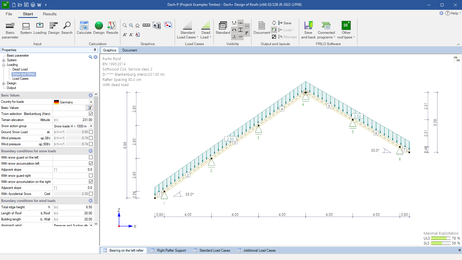 User interface
 -
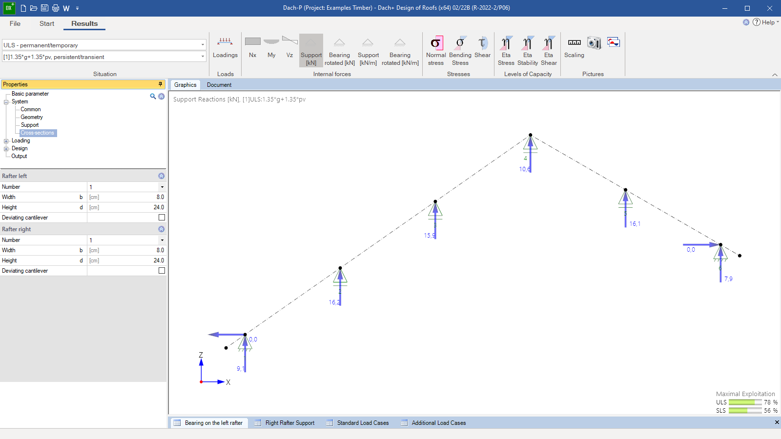 Graphical representation of the results
 -
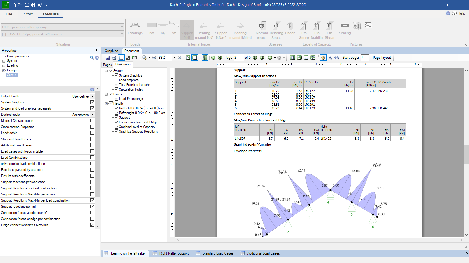 Output document with graphic
Purlin-/Rafter Roof
DPD+
The program DPD+ can be used to calculate purlin roofs and rafter roofs as well as mixed roofs of both types such as purlin roofs with ridge joints.
The purlins on the left and right roof sides are designed as continuous beams under bending stress. Asymmetrical structural systems are possible.
Discover now more programs from the section Roof!
SHOW MOREMaterial
- Softwood
- Hardwood
- Glulam
Structural system
- Both sides of the roof consist of straight continuous rafters having an inclination and the same cross-section over several spans without intermediate joints
- The roof pitch, the cross-sections and the span lengths can differ on the left and right side
- Different rafter spacing on the left and right side
- The cantilevers can have a different cross-section
- The projection over the ground plan of the house can deviate from the cantilever geometry
- The supports are sway in the horizontal and vertical direction or restrained. The restraints can be defined as being rigid or elastic
Loads
- Automatic generation of the loads from self-weight, snow, and wind
- Additional user-defined loads as uniformly distributed loads, concentrated loads or trapezoidal loads
- Man loads as well as wind uplift at projections
- Accidental snow load is optionally available
- Loads from photovoltaic arrays
- To reduce the computing time for more extensive systems, various settings are available for the grouping of load cases and load combinations
Design settings
Optionally selectable:
- Verification of the wind suction resistance
- Seismic load combinations
- Hot design
- As a standard option, only positive deflections are verified on the cantilever (on short cantilevers, the negative deflection is often decisive in terms of calculation, but this is not always desired)
Effective length for buckling and lateral buckling separately for the cold and hot design:
- Default setting: calculation of the effective length for buckling from the eigenvalue solution of the plane system. Assumption of continuous lateral support with limitation of the maximum effective length for buckling in the rafter plane to 0.9 times the component length
- Alternatively, setting the effective length to the length of the member, the component or a default value
Connection details
Base
- Connection with a notch or pole plate
- Connection with a straight or haunched cleat
Purlin support
- With birdsmouth joint
- With nailed cleat
Document file formats
- Word
- Printer
Output
- User-defined output with various setting options for tables and graphics
- Result graphics with internal forces, stresses, or displacements can be specifically transferred to the output document using the camera button
- Support reactions are optionally put out for each load case, each action or as min/max values, either for each rafter or per linear metre
Transfer options
- System transfer to the other Roof programs
- System transfer to the RSX Frame program
- Transfer of support reactions to the Continuous Timber Beam program HTM+
- Transfer of support reactions to the Continuous Steel Beam program STM+
- Transfer of support reactions to the Timber Column program HO1+
- Direct interface to the CAD programs from SEMA
Timber construction
- DIN EN 1995
- ÖNORM EN 1995
- NTC EN 1995
- BS EN 1995
- PN EN 1995
- EN 1995
Support resources
News
FRILO launches version 2024-2 with powerful updates for structural analysis and design
Highlights include the optimised design of Schöck Isokörbe®, the advanced integration of DC foundation engineering programs into the FRILO environment and new RSX interfaces for detail verifications in steel construction.
Load determination for eight-floor perimeter block development with FRILO Building Model
Find out how the structural engineers at bauart Konstruktions GmbH determined the loads for an eight-floor perimeter block development in Frankfurt’s Europaviertel district using the GEO from FRILO.