
Timber Wall Diaphragm
The “Timber Wall Diaphragm” program is used to analyze wall panels (diaphragms) according to Eurocode 5 and its National Annexes. The variety of definable systems ranges from simple walls with regular rib spacing and identical paneling on both sides to irregular column placement with different paneling and different panel grids on each side. A horizontal butt joint can be defined for an individual, several or all panels. Different materials can be assigned to each rib and each paneled side.
Only available in FRILO Professional und FRILO Ultimate
Core capabilities
Material
Rib materials
- Softwood of the strength classes C14 to C50
- Hardwood of the strength classes D18 to D80
- Glulam of the strength classes GL20c/h to GL32c/h
Paneling materials
- Plywood
- Oriented strand board
- Chipboard
- Fibreboard
- Gypsum board
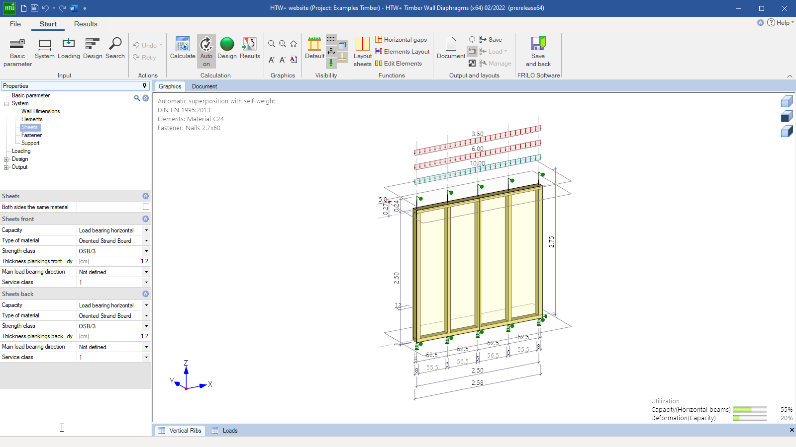
Structural system
- Simple walls with regular and irregular rib spacing
- Identical or different paneling on either side
- Freely selectable position of each column
- Identical or different panel grid on either side
- Horizontal butt joint available for individual, several or all panels
- Identical or different materials and/or cross-sections on either paneled side and for each rib
- Vertically continuous edge ribs are available (without a base frame to bear transverse pressure)
Loads
- Vertical loads:
- concentrated
- uniformly distributed
- trapezoidal loads
- Horizontal concentrated load in the direction of the wall axis
- Area loads over the wall height in the transverse direction
- Accidental loads
- Seismic loads
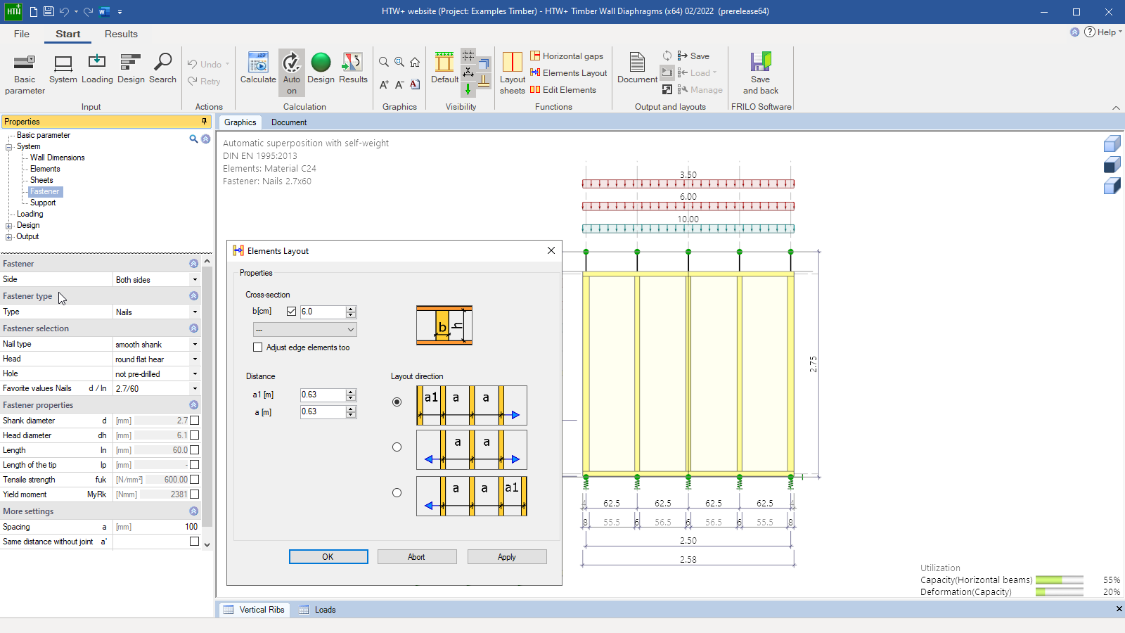
Fasteners
- Nails
- Bolts
- Brackets
- Glue
Design
The paneling is calculated as a shear panel (9.2.4.2 method A), which bears the horizontal loads in the direction of the wall axis. Vertical forces are borne by the vertical ribs. In addition to the standard safety verifications, also the decisive anchoring forces for the position stability and the deformations are calculated in the serviceability verifications including creep.
The stiffnesses of the fasteners and the support, the bending stiffness and the shear stiffness are taken into account. The stiffness types including the required reductions are calculated for all components. Support stiffness (specified by the user) is handled with separate tension and compression springs on the edge ribs. The compression springs of the base frames can be calculated optionally. The verifications of the stresses and the stability of the ribs are performed as per 6.3.2 and the transversal rib compression as per 6.1.5. The verification model (base frame pressure or bearing stress) is optionally selectable.
The verifications of the paneling (shear) and the fasteners include the relevant increase factors and reduction factors (9.2.4.2). The application of the increase factor can optionally be disabled. If paneling on both wall sides was defined, different stiffness on each side can be taken into account (optionally with consideration of real stiffness). Serviceability verifications are performed based on the calculated stiffness.
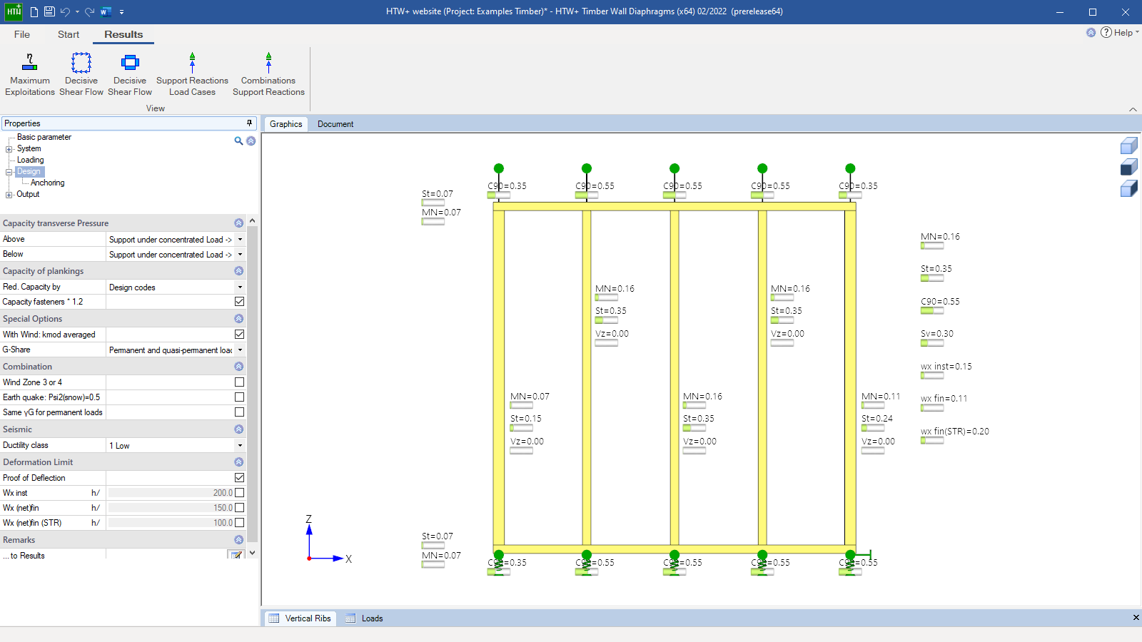
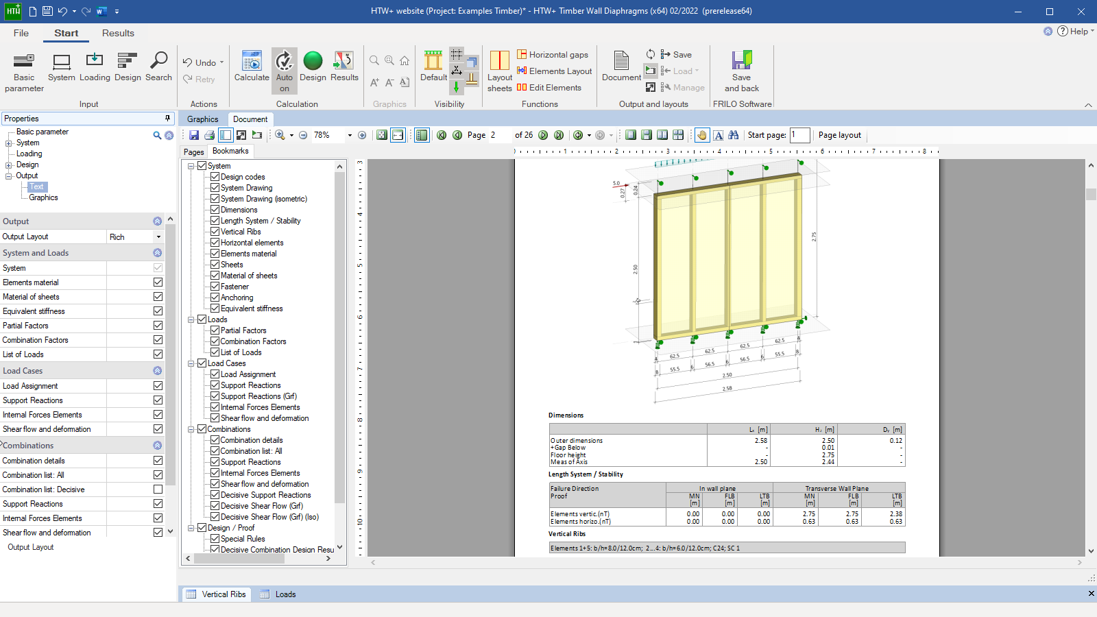
Output profile
- User-defined scope
- Additional result graphs:
- Maximum utilization for all verifications
- Decisive shear flow in the front and rear panelling
File formats
- Word
- Printer
Würth panel anchors
To anchor the end ribs, the program supports the design of two-piece Würth panel anchors.
Timber construction
- DIN EN 1995
- ÖNORM EN 1995
- NTC EN 1995
- BS EN 1995
- PN EN 1995
- EN 1995
- DIN 1052
Support resources
News
Corporate headquarters as reinforced concrete skeleton structure
With the construction of a new corporate headquarters, Heidelberg Materials has demonstrated the remarkable range of reinforced concrete as an attractive building material. FRILO and Allplan were used by the structural engineers.
FRILO launches version 2024-2 with powerful updates for structural analysis and design
Highlights include the optimised design of Schöck Isokörbe®, the advanced integration of DC foundation engineering programs into the FRILO environment and new RSX interfaces for detail verifications in steel construction.