
-
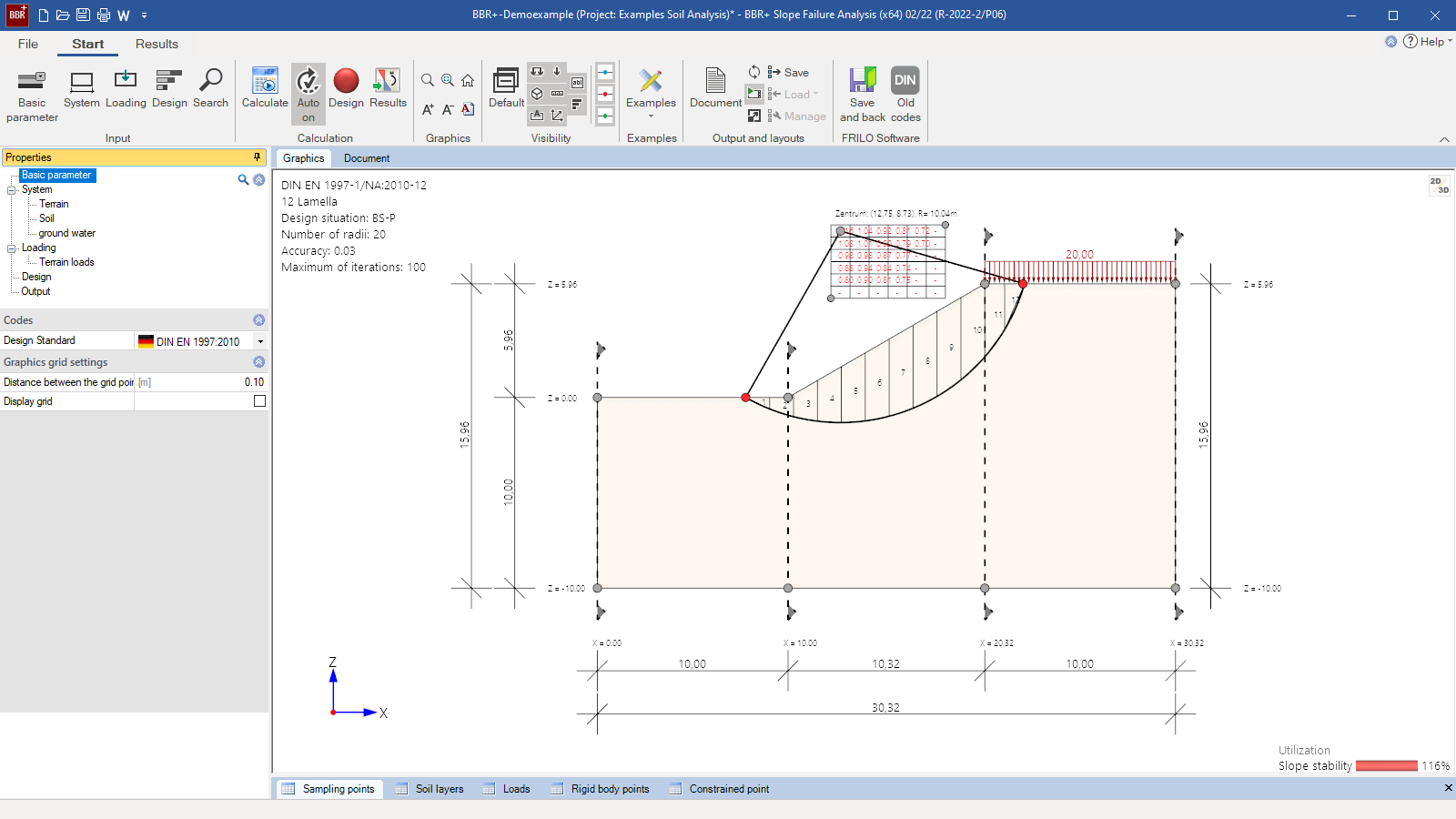 BBR+ user interface
 -
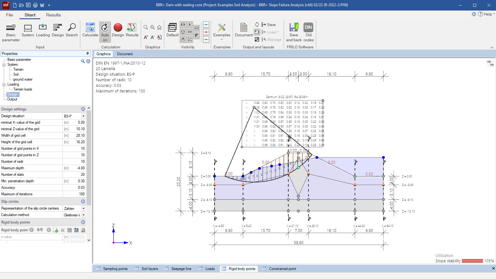 Self-contained layer of soil as an impermeable core within an embankment
 -
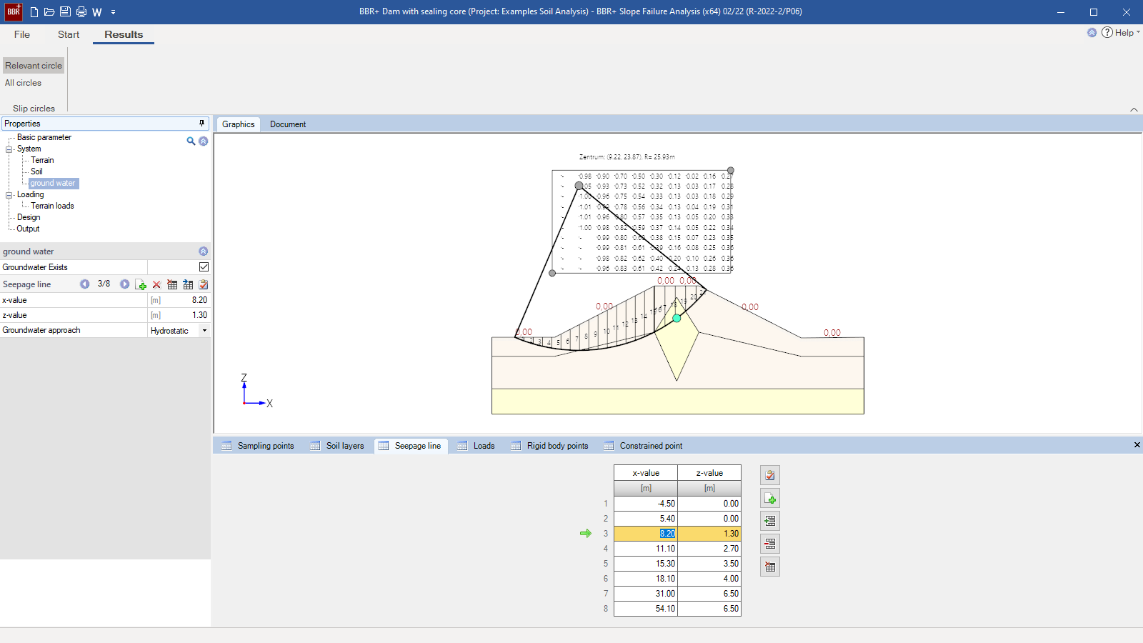 Definition of a seepage line
Slope Failure Analysis
BBR+
BBR+ can be used to calculate the slope failure safety of a defined ground surface in the form of a utilization ratio. The calculation is based on the method of slices by Bishop. Utilization is calculated for a slip circle, which is determined by its centre and its radius. Depending on the specifications made by the user to limit the possible slip circles an automatic slip circle variation can be performed. Only clockwise rotating slip circles, which cause the slope to slide to the left, are examined
Discover now more programs from the section Foundation Engineering!
SHOW MOREStructural system
- Definition of any kind of abrupt typographical change
- Hills, valleys as well as free groundwater tables in the form of lakes can be modelled
- Definition of the soil layer model on the vertical section via sampling points
- Alternative definition of the soil layer model by free polygonal modelling of the soil layer boundaries
Soil
- Any number of soil layers with polygonal boundaries
- Freely selectable soil parameters
- Definition of self-contained soil layers (e.g. lenses or impermeable cores)
- Classification of soil types as per DIN 18196 with admixtures
Ground surface
- Any kind of polygonal ground topography
- It is possible to model several hills and valleys
Groundwater
- Freely selectable presence of groundwater in the form of a polygonal seepage line
- Free water tables in the form of lakes
- In the slope failure calculation, groundwater can be considered either via the pore water pressure as an internal force or hydrostatically via the water pressure as an external force
Loads
- Application of line, area and moment loads
- Line loads can also act horizontally
- Application of loads as surface loads or, optionally, as acting at a freely selectable depth z
- Free assignment of loads to a type of action as per EC 0.
- Verification method 3, where partial safety factors are applied to actions and the geotechnical parameters, is used.
Customisable design
- Selection of the design situation (persistent BS-P or transient BS-T)
- Definition of a centre grid for the slip circle variation
- Definition of the number of slices
- Limitation of the slip circle variation by defining the required minimum depth to which the slip circle must penetrate the ground, the maximum number of variations and the number of radii to be investigated
Slip circles
- Representation of the utilization in the variation grid in the form of numerical values or a colour scheme
- Calculation with automatic slip circle variation by specifying a fixed slip circle geometry
Rigid body points
- They describe the lower endpoints of rigid structures such as foundations, anchors, piles etc.
- They are used to limit the slip circle variation
- They must lie inside the decisive slip circles
- Rigid bodies cannot be intersected by the slip circle above their endpoints (rigid body points)
Constraint points
- To limit the slip circle variation
- One or two constraint points are possible
- Positioning of constraint points, e.g. at the slope bottom
Document file formats
- Word
- Printer
General
- Various output profiles are available for selection (brief, detailed, user-defined)
- Detailed output of the force relationships at the slices
- Result graphics can be put out optionally
Verifications
- Detailed tabular compilation of all slice forces
- Comparison of the driving and retaining moments around the decisive slip circle centres with associated utilization
Geotechnical standards
- DIN EN 1997
- ÖNORM EN 1997
- DIN 1054 in conjunction with DIN 4084
Support resources
News
FRILO launches version 2024-2 with powerful updates for structural analysis and design
Highlights include the optimised design of Schöck Isokörbe®, the advanced integration of DC foundation engineering programs into the FRILO environment and new RSX interfaces for detail verifications in steel construction.

Load determination for eight-floor perimeter block development with FRILO Building Model
Find out how the structural engineers at bauart Konstruktions GmbH determined the loads for an eight-floor perimeter block development in Frankfurt’s Europaviertel district using the GEO from FRILO.