
Foundation
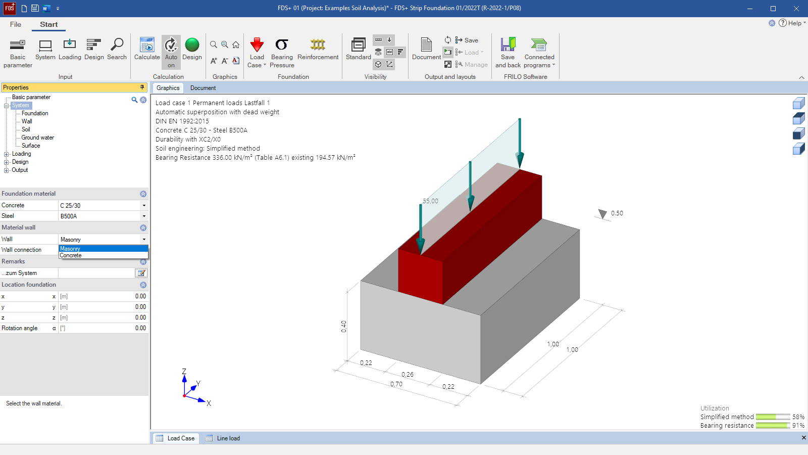
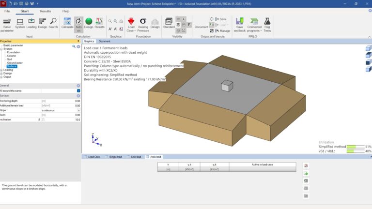
With the “Foundation” module strip foundations, pad foundations, mast foundations, raft foundations and isolated foundations can be analyzed and designed. reinforcement layout, and bearing resistance failure. Außerdem können allgemeine Grundbruchnachweise für mehrschichtige Böden ober- und unterhalb der Fundamentsohle geführt werden. In addition, verifications for general bearing resistance failures can be performed for multi-layer soils above and below the foundation slab.
Also available in FRILO Professional, FRILO Ultimate, FRILO Geotechnic Professional und FRILO Geotechnic Ultimate
Core capabilities
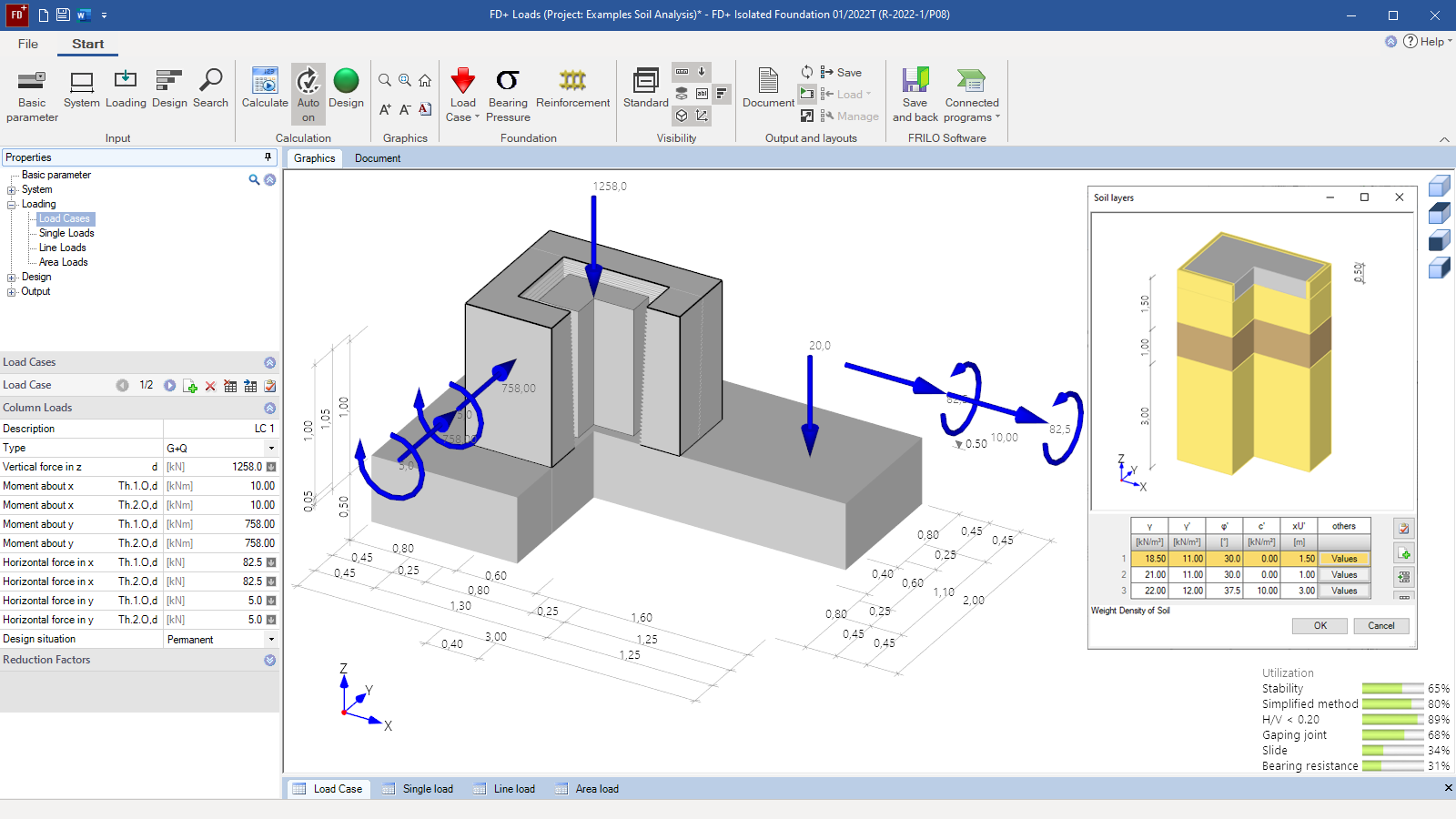
The feature can be used to verify square, rectangular and circular foundations cast with or without sleeve or pocket. External loads can optionally apply centrically or with a uniaxial or biaxial eccentricity. The solution calculates the soil pressure underneath the four corner points and the position of the neutral axis in combination with a gaping joint. The required flexural reinforcement is calculated for the foundation and the punching shear resistance is verified. The required reinforcement for the connection and the pocket is optionally determined. All required geotechnical verifications are optionally performed in the ultimate limit state and in the serviceability limit state.
Material
- Reinforced concrete with selectable concrete qualities and steel grades
- Different materials for the foundation and the column
Structural system
- Square, rectangular and circular foundations
- Optionally with eccentric column
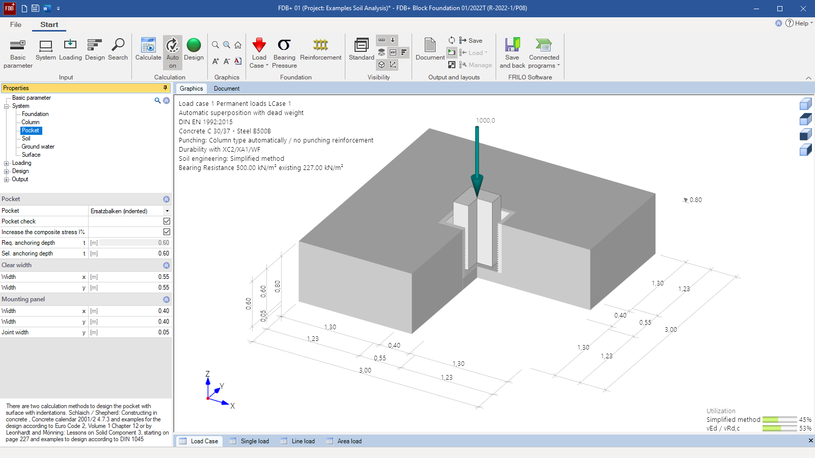
- Optionally with interior and exterior base (pocket)
- Smooth or toothed pocket surface (design in accordance with Leonhardt or Schlaich/Schäfer)
- Haunches on the top of the foundation
Soil
- Any number of horizontal layers
- Freely selectable soil parameters
- Permissible base pressure resistance based on empirical values of DIN 1054
- Earth pressure approach
- Inclined foundation base
Ground surface
- Horizontal or continuously ascending
- Any number of polygonal ground-surface sections
Groundwater
- Stagnant groundwater can optionally be taken into account at any height level
Loads
- Any column loads for biaxial loading, if applicable:
- Vertical concentrated load V
- Horizontal concentrated load in the x- or y-direction (optionally applying to the top edge of the pocket or the foundation)
- Concentrated moments about the x-axis and the y-axis
- Block loads (quadrant loads)
- Any additional loads applying to the foundation as concentrated loads, line loads or area loads
- For individual loads on the foundation, the following can be defined by the user:
- the load components vertically
- the load components horizontally in the x and y directions
- the moments around the main axes
- the position of the load application point
- Free assignment of loads to types of actions according to EC 0 as well as to concurrency and alternative groups
- General separation of the definition of design loads and of characteristic loads with automatic load case combination
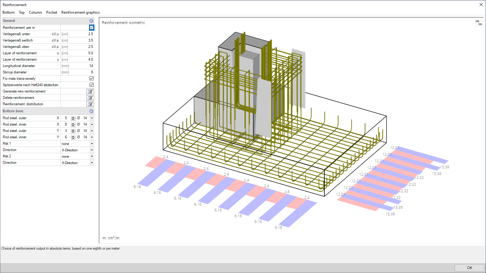
Reinforced concrete design
- Punching shear analysis with/without punching shear reinforcement
- Bending design
- Shear force design
- Pocket design with strut-and-tie models
- Durability verification via exposure classes
- Consideration of different minimum reinforcement quantities
- Any kind of reinforcement and any arrangement definable in the reinforcement dialog
- Analysis of internal forces, bending moments, and shear forces can be performed on any user-defined sections
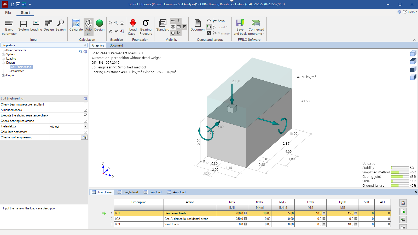
Geotechnical verifications
- Simplified verification with base pressure resistances (either user-defined or based on tables of DIN 1054)
- Optional verifications using the accurate calculation method:
- Overturning
- Sliding
- Ground failure
- Optional settlement verification
- Serviceability via the verification of the gaping joint and torsion
- Seismic ground failure verification
- Ground failure punching shear verification
- Bearing capacity analysis of the foundation soil with a table of design values of the base pressure resistance
- Slope failure verification separately for all 4 failure directions
General output
- Various output profiles available for selection (brief, detailed, user-defined)
- Selectable graphic scales and font sizes
- Detailed output of individual load cases
- Overview of the decisive load case combinations and their assignment to the design situation (persistent, transient, accidental and earthquake)
- Reinforcement sections can optionally be output in the form of a reinforcement plan
- Graphical and tabular output of internal forces in both main directions in any cross-sections
Reinforced concrete design
- Decisive base pressure distribution for the individual design calculations
- Bending design in the x- and y-direction at the top and bottom of the foundation with detailed graphical and tabular output
- Graphical representation of the reinforcement distribution and, if applicable, staggered reinforcement quantities
- Detailed graphical and tabular representation of the punching shear design
- Detailed output of the pocket design, if applicable
- Details on calculated lapping and anchorage lengths
- Reinforcement drawings
Geotechnical verifications
- Tabular and graphical output of the selected decisive actions and base pressures for each selected geotechnical verification
- Verifications in the ULS (simplified with base pressure, overturning, sliding, ground failure)
- Verifications in the SLS (first and second core range, settlements, and torsion)
- Graphical output of the internal forces along the main axes
File formats
- Word
- Printer
Transfer options
- Slabs by Finite Elements
- Punching Shear Analysis
- Block Foundation
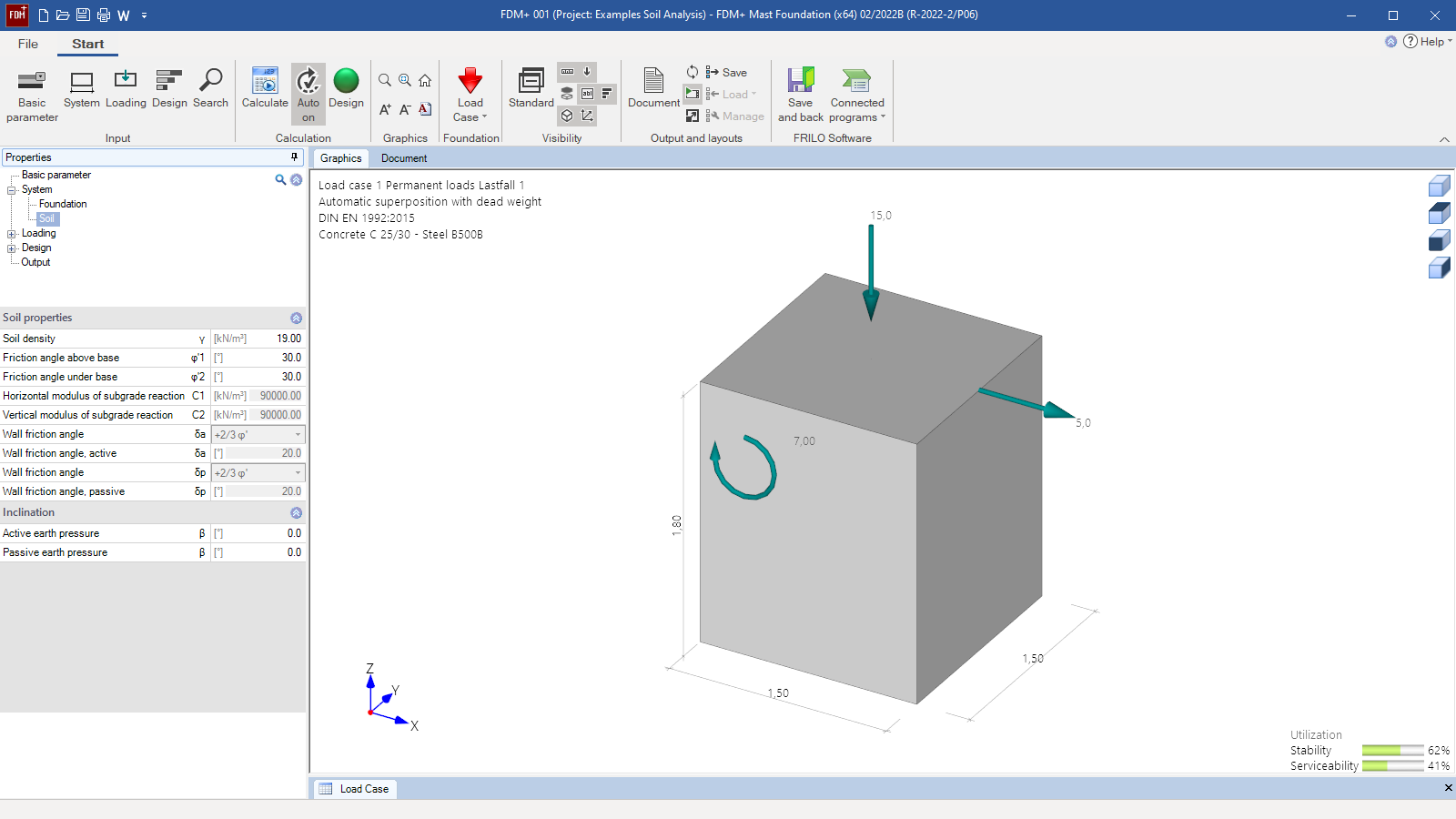
- Mast Foundation
- Strip Foundation
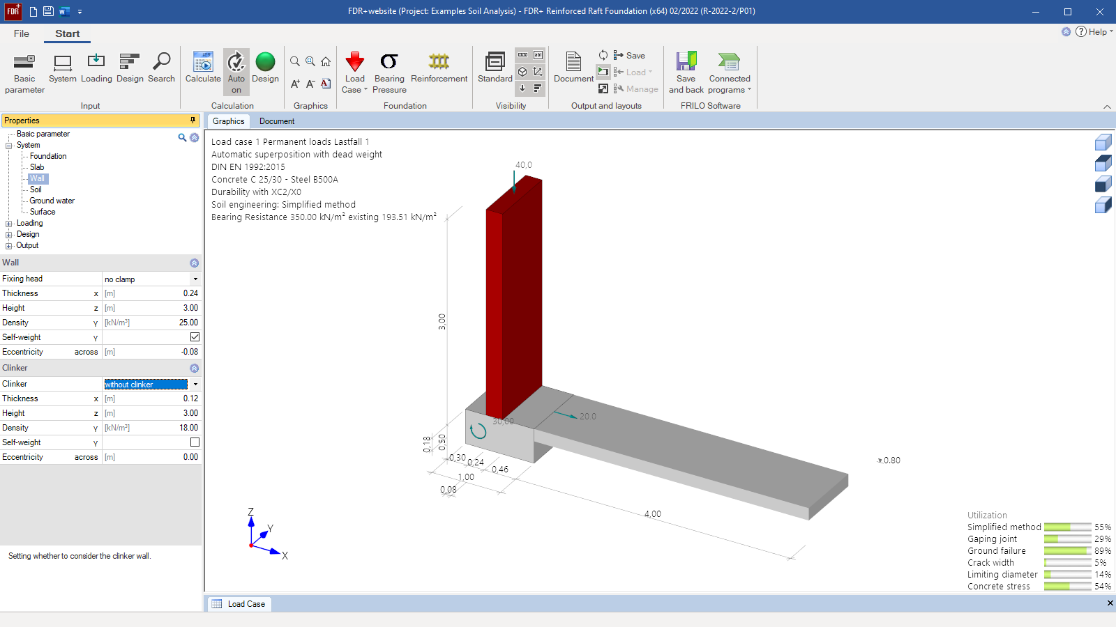
- Reinforced Raft Foundation
- Ground Failure Analysis
- Beam on Elastic Foundation
- Soil Settlement
Load import from
- Framework RSX
- Building Model GEO
- FRILO column and frame programs
- SCIA Engineer
Foundation engineering
- EN 1997
- DIN EN 1997
- ÖNORM EN 1997
- PN EN 1997
- NF EN 1997
- DIN 1054
- DIN 4017
- DIN 4019
- ÖNORM B 4435-2
Reinforced concrete
- EN 1992
- DIN EN 1992
- ÖNORM EN 1992
- PN EN 1992
- NF EN 1992
- BS EN 1992
- DIN 1045
- ÖNORM B 4700
News
Raising foundation design to a new level
The new FD+ PRO module is an add-on which, with the purchase of an additional licence, significantly extends the scope of foundation design for the FD+, FDS+, FDB+ and GBR+ programs.

Corporate headquarters as reinforced concrete skeleton structure
With the construction of a new corporate headquarters, Heidelberg Materials has demonstrated the remarkable range of reinforced concrete as an attractive building material. FRILO and Allplan were used by the structural engineers.