


-
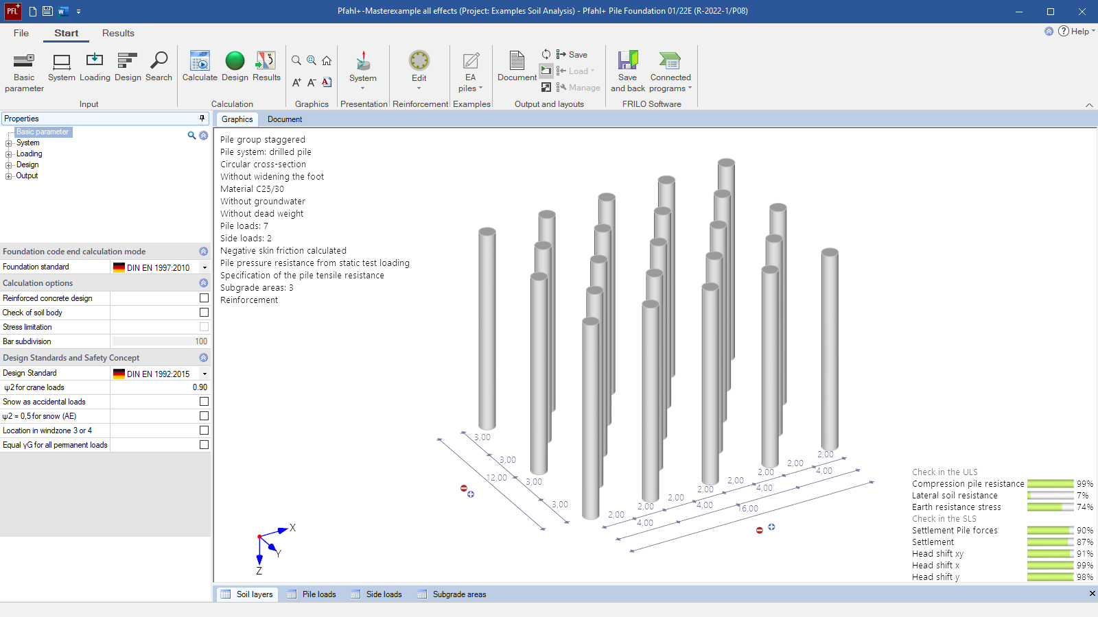
 Pfahl+ user interface
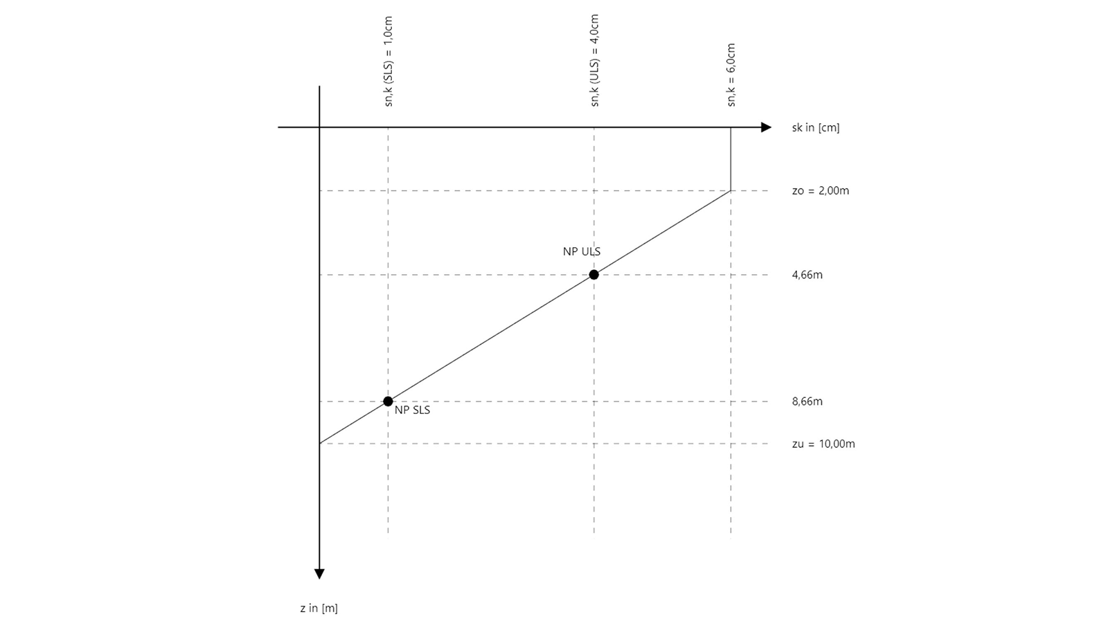
 - Behaviour of the negative skin friction
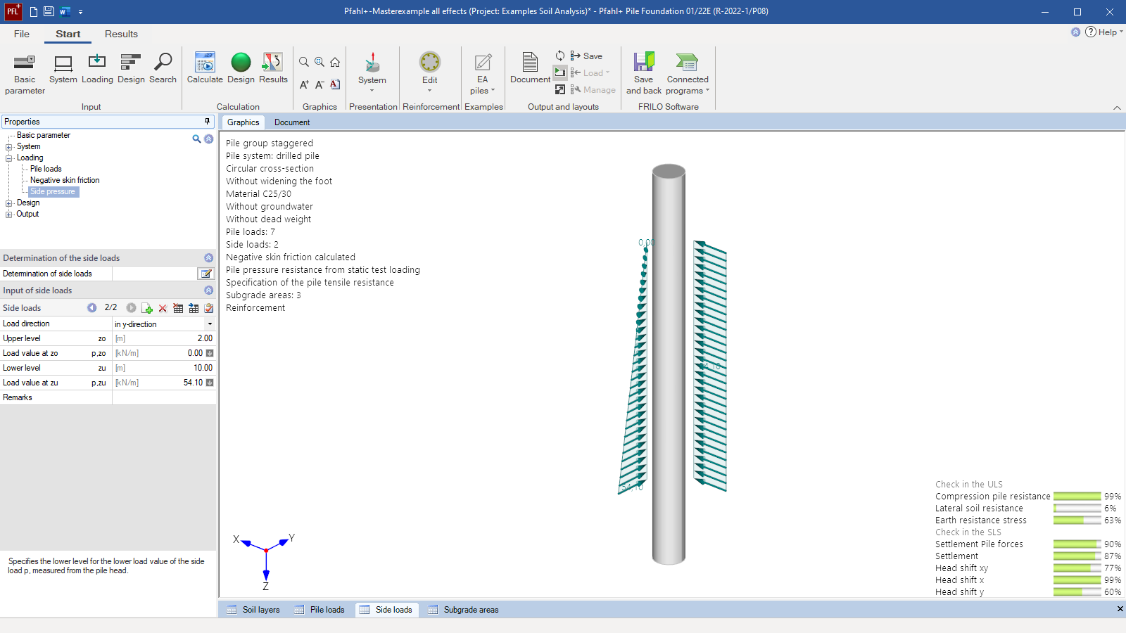
- Lateral pressure on the piles
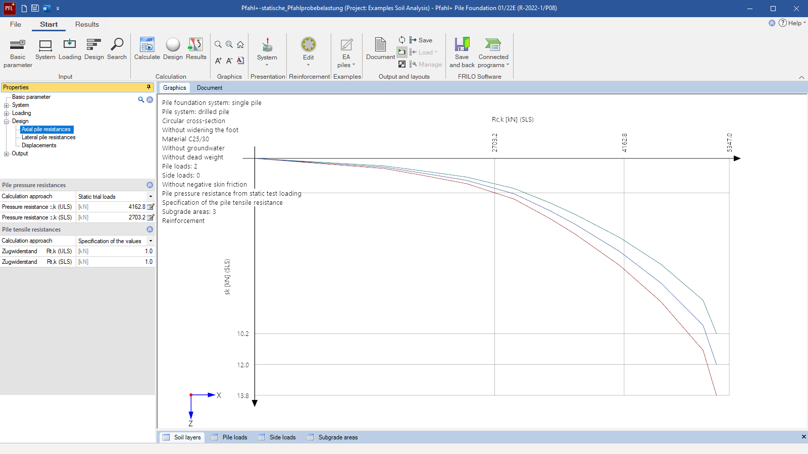
- Resistance-settlement curves based on the test loading of the piles
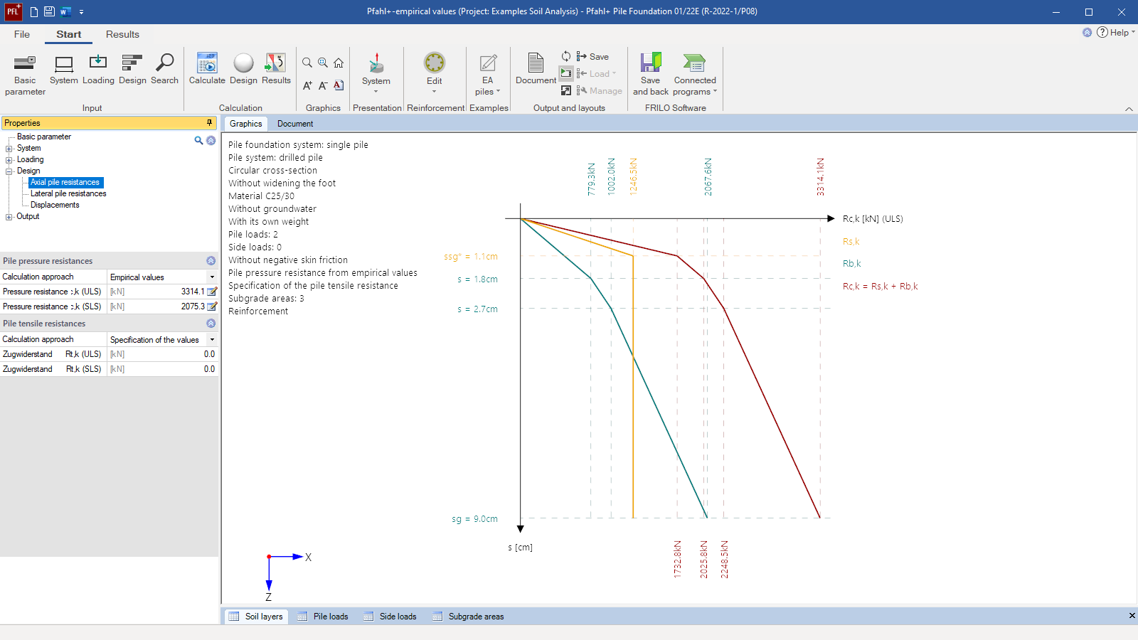
- Resistance-settlement curves based on empirical values taken from the recommendations of the pile work group “EA-Pfähle”
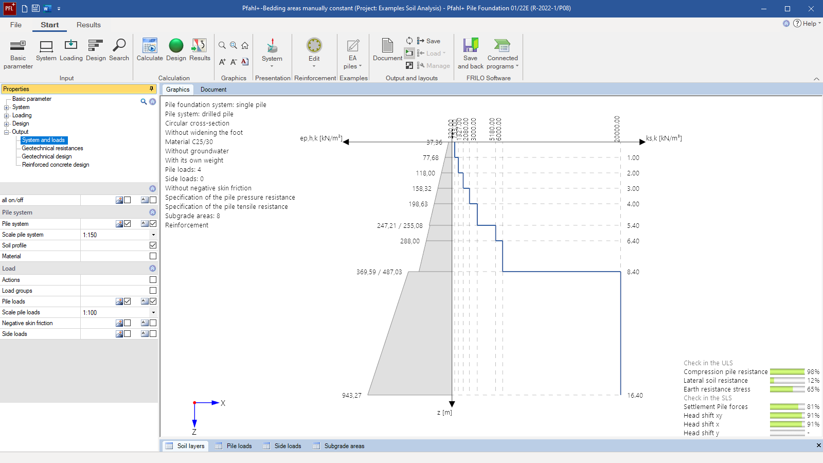
- Definition of subgrade areas
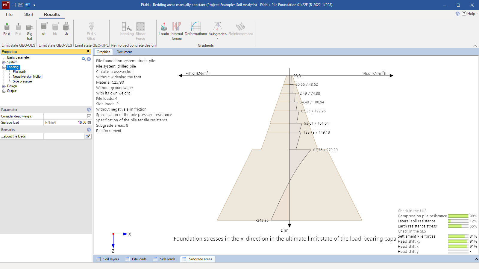
- Subgrade verification by comparison of the horizontal stresses and the earth resistances
Pile Foundation
Pfahl+
With the program Pfahl+, the internal and external load-bearing capacity of bored piles, micro drilled piles, reinforced concrete or steel prefabricated piles as well as ductile cast iron piles can be verified.
Both the soil settlements in the vicinity of the pile and, derived from this, a negative skin friction as well as the lateral pressure acting on the piles can be taken into consideration. The axial pile resistances, due to skin friction and end-bearing pressure, can optionally be determined either by evaluating static or dynamic pile test loads or based on empirical values given by the recommendations of the pile work group “EA-Pfähle” separately for the serviceability limit state (SLS) and the ultimate limit state (ULS).
Discover now more programs from the section Foundation Engineering!
SHOW MOREStructural system
Basic parameters:
- Active/interactive reinforced concrete design
- Uplift resistance verification of tension piles, if applicable
- Optionally selectable automatic stress adaptation
Structural system:
- Definition of pile groups to derive the actions from lateral pressure
- Definition of the pile system (cross-section, shaft length, toe expansion, if applicable)
- Definition of the pile material (optionally with creep effects)
- Durability verification via exposure classes
Soil:
- Any number of horizontal layers
- Freely selectable soil parameters
- Assignment to soil types (backfill, soft layer, bearing layer)
- Special parameters for the calculation of settlements and negative skin friction (via total or effective stresses)
Ground surface:
- Horizontal ground top edge
Groundwater:
- Stagnant groundwater can optionally be taken into account. The buoyant unit weight of the water-saturated soil is automatically considered.
Loads
- Any pile loads in the form of vertical or horizontal head loads or head moments along the two main axes. Free assignment to types of actions according to EC 0 and to concurrency and alternative groups, if applicable.
- Optionally, a surface load can be defined in the immediate vicinity of the pile.
- Via interface to the program Soil Settlement SBR+, the soil settlement in the pile vicinity and, optionally, the generated negative skin friction can be calculated automatically.
- Via interface to the program Earth Pressure EDB+, optionally, an action caused by lateral pressure due to flowing soil can be calculated automatically.
Superposition:
The individual load cases are automatically superimposed and the decisive design combination is assigned to each verification.
Settings
- Optional non-linear design in a second-order analysis with non-linear internal forces and material behaviour
- Continuous reinforcement over the total length or over specific sections
- Special setting options for serviceability (minimum eccentricities, min As for compression members)
Axial pile resistances
- Determination by specifying characteristic total resistances (separately for compression and tension)
- Evaluation of static pile test loads (data-entry dialog and automatic/specific evaluation of any number of measuring series) → Resistance-settlement curve
- Evaluation of dynamic pile test loads (data-entry dialog and automatic/specific evaluation of any number of measuring series) → Resistance-settlement curve
- Determination of the resistance-settlement curve from empirical tabular values for end-bearing pressure and skin friction specified in the recommendations of the pile work group “EA-Pfähle”
Lateral pile resistances
Determination by specifying subgrade reaction moduli and subgrade areas:
- Automatic derivation of the subgrade from soil layers and soil properties
- User-defined subgrade areas
- Optional automatic modification and setting of the subgrade areas with calculation functions (constant, linear, parabolic)
- Automatic inclusion of the two- and three-dimensional earth resistances in the subgrade areas
Displacements
- User-defined specification of the greatest permissible displacements in the three main directions and as a resultant
Document file formats
- Word
- Printer
Output
- Comparison of pile settlement and soil settlement with representation of the neutral points in the serviceability and ultimate limit states for the derivation of negative skin friction
- Mapping of the resistance settlement curve for the end-bearing pressure, the skin friction, and the pile bearing capacity derived from empirical values or test loading
- Design internal forces for compression and tension piles in the serviceability limit state SLS and the ultimate limit state ULS.
- Mobilised subgrade stresses, both in the direction of the main axes and as a resultant
- Superposition of the subgrade stresses with the earth resistance to represent the required stress limitation and the relocations of the subgrade stresses to greater depth if applicable.
- Deformation of the pile along the main axes and as a resultant in the SLS
- Representation of the selected and required reinforcement
Transfer options
- Soil Settlement SBR+ (calculation of the decisive settlement in the pile environment to determine the negative skin friction)
- Earth Pressure Calculation EDB+ (calculation of the decisive lateral earth pressure and the earth resistances)
- Reinforced Concrete Column B5+ (calculation of the pile as a column on elastic foundation in accordance with the subgrade reaction modulus method)
Geotechnical standards
- DIN EN 1997
- ÖNORM EN 1997
- BS EN 1997
Design
- DIN EN 1992
- ÖNORM EN 1992
- BS EN 1992
Support resources

News

FRILO launches version 2024-2 with powerful updates for structural analysis and design
Highlights include the optimised design of Schöck Isokörbe®, the advanced integration of DC foundation engineering programs into the FRILO environment and new RSX interfaces for detail verifications in steel construction.
Load determination for eight-floor perimeter block development with FRILO Building Model
Find out how the structural engineers at bauart Konstruktions GmbH determined the loads for an eight-floor perimeter block development in Frankfurt’s Europaviertel district using the GEO from FRILO.
Events
You may also be interested in these programs

