
Plate
The “Plate” module is suitable for the calculation of load-bearing plate-type structures of any kind in accordance with the Finite Elements Method FEM. The powerful graphical user interface provides numerous functions for the fast and efficient processing of this complex calculation model. Any floor plan with straight and curved edges including block-outs can be modelled. Floor slabs typical in massive building construction are mapped as plates with all structurally relevant components and loads. Base slabs and intermediate floor slabs as well as a mixture of both can be defined. The calculation of base slabs is based on the subgrade reaction modulus method.
Also available in FRILO Professional und FRILO Ultimate
Core capabilities
Data input
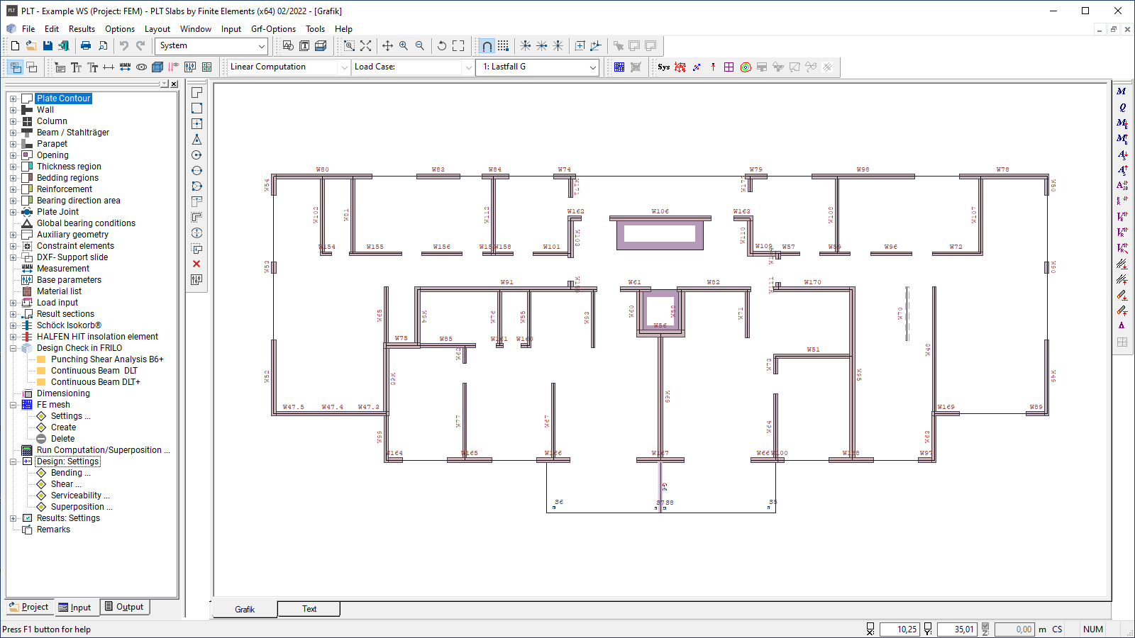
Most data are entered interactively in the graphical user interface. To support this, DXF slides can be read in and self-defined auxiliary structures or auxiliary grids can be used. Thanks to a locally definable coordinate system and direction-oriented data entry, points/components can be defined easily and accurately via the graphical user interface or by entering numerical coordinates. The Undo/Redo functionality allows work steps to be undone/restored, which supports a safe and effective workflow. Various import options, for example via the FRILO BIM-Connector®, top off the data input.
Structural system
The load-bearing behaviour of the slab is influenced by:
- Globally adjustable basic parameters such as
- Relevant standards
- Concrete qualities and steel grades
- Durability specifications by defining concrete properties, exposure classes, permissible crack widths and limit diameters
- Reinforcement layer for the definition of the centre of gravity of the upper and lower reinforcement
- Specification of torsional rigidities to define torsionally resilient or torsionally stiff slabs
- Specification of the subgrade reaction modulus to define springs for the reaction modulus method, which is used to calculate base slabs
- Area definitions such as
- Supporting direction areas for the definition of uniaxial supporting areas
- Subgrade areas for elastic foundation, optionally with subgrade failure
- Reinforcement areas for the definition of a basic reinforcement and to specify rotated directions for the reinforcement
- Thickness areas to describe partial slab areas with different thicknesses, concrete properties, and adjustable torsional rigidity behaviour
- Line-type and point-type elements such as
- Wall and columns for the definition of support springs – see support conditions
- Joints for the definition of the different line-shaped degrees of freedom
- Beams for the definition of line-shaped bracing in the slab
Loads
Loads are defined in various load cases. In this process, a unique group of actions is assigned to each load. All loads in a load case are assumed to apply always simultaneously. By assigning individual loads to an alternative group, these loads can be defined as to exclude each other.
All possible combinations are automatically considered in the calculation. The user can exclude particular load cases from the superposition.An exception to this is the non-linear calculation with tension spring failure, which requires that the load combinations be clearly specified by the user – see <Design>.
Load types:
- The available loads are point, line and area loads. For line and area loads, a distinction can be made between constant and non-constant loading
- In addition, temperature loads can be taken into account where the temperature difference between the top and bottom of the slab is considered
Support conditions
Point or line supports are generated via the components column or wall and can be included as rigid or elastic structures in the calculation. The user can freely define the elastic support or have it automatically determined from the geometry and the material properties.
Via the function “Global support condition” the respective support condition can be globally applied to all supports separately for walls and columns. The calculation with spring failure for columns and walls is possible.
Mesh properties
The automatic mesh generator allows the generation of meshes with triangular and rectangular elements as well as mixed meshes. The user can freely define which elements and which design points should be used in the calculation. When defining the design points, the element size can be specified.
By entering constraint geometries, the user can further influence the mesh generation. Freely definable lines, points, and circles, but also automatic constraint geometries for wall corners, walls, and columns are available.
FE analysis
For the calculation of thin slabs, shear-rigid hybrid elements in accordance with the Kirchhoff-Love Plate Theory are available. By combining displacement and stress assumptions, a high accuracy of the calculated internal forces is achieved. Alternatively, elements according to Reissner-Mindlin can be selected, which allow the consideration of shear deformations.
Bending design of reinforced concrete
The design of the reinforcement is performed in accordance with the Baumann method. A cracked slab element is used as a model. The design approach assumes an orthogonal mesh reinforcement. The reinforcement direction can be arbitrary.
Shear design of reinforced concrete
The shear design is based on a strut-and-tie model. In this case, the longitudinal reinforcement is taken into account to determine the shear force resistance without shear reinforcement.
Structural safety
- Bending and shear design of the slab and the beams
- Deformation of the slab in state I
- Determination of the soil pressures
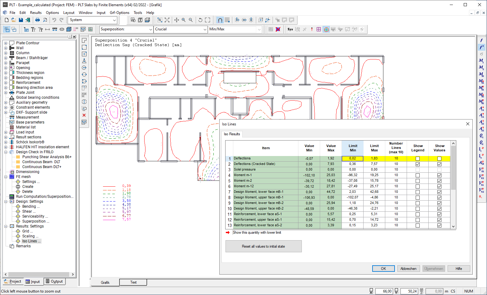
Serviceability
Deformations in state II
- By ticking the option “Determine deflection”, the verification of the deflection in state II is enabled
- The deflection in state II is calculated for the quasi-permanent combination
- An exact calculation of the deformation is subsequently performed by numerical integration of the curvatures
- The moment curvature lines (Mk-lines), which are created for a specific cross-section with consideration of the crack formation and the contribution of the concrete in tension, form the basis for this integration
- As the calculation depends on the existing reinforcement, the intended reinforcement can already be considered in the calculation by entering a global or local reinforcement
- The user can optionally specify the influence of shrinkage and creep or have it calculated by the software
Crack width, permissible limit diameter
- The calculation of the existing crack width and/or the permissible limit diameter of the longitudinal reinforcement depends on flexural tension reinforcement ratio as per EN 1992-1-1, sections 11.2.3 and 11.2.4.
Special verification methods
ISO element (Schöck)
General
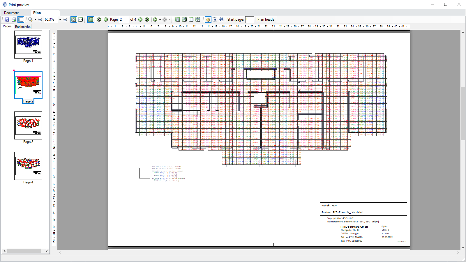
An extensive graphical and tabular output to create the structural analysis documents in A4 format is provided. Moreover, all graphics can be put out in the so-called drawing format. For the drawings, various title block templates can be defined and used subsequently.
Output
The output profile offers a variety of setting options to create an individual structural analysis document. The scale is freely selectable.
Transfer options
- Continuous Beam (Transfer of the node loads from the FE analysis)
- Punching Shear Analysis
- Pile Foundation
Import options
- Data can be imported into the PLT program from various CAD programs
- Via a direct interface to GLASER -isb cad-, CAD data can be read in and further processed on this basis
- Data from ALLPLAN can be imported if the structural components have been processed appropriately in Allplan
- Via a DXF interface, geometry data in the form of auxiliary constructions can be imported from all common CAD programs. These data can be used in the program via a snap function supporting the easy entry of the geometry
Export options
- Graphical representations and results can be exported to a DXF file
- Reinforcement data are transferred in an open data format called The use of these data in the target system is independent of the available system functions. The ASF format allows the transfer of all data produced in the FEM calculation. With these data, all results can be visualised in the ALLPLAN CAD system and used interactively in the creation of the reinforcement design
- A special interface has also been set up for the GLASER -isb cad- software, which can be used to generate the reinforcement
Reinforced concrete
- DIN EN 1992
- DIN 1045/DIN 1045-1
- ÖNORM EN 1992
- ÖNORM B 4700
- UNI EN/NTC 1992
- BS EN 1992
- PN EN 1992
Masonry
- DIN EN 1996
- DIN 1053-1/-100
- ÖNORM EN 1996
- BS EN 1996
Materials for steel columns
- DIN EN 1993
- DIN 18800
- ÖNORM EN 1993
- BS EN 1993
Slabs
All floor slabs can be defined as reinforced concrete slabs. Different thicknesses, different concrete qualities, and different load-bearing directions (uniaxial and biaxial) as well as torsionally resilient and torsionally stiff elements can be defined. The slab is supported by walls and columns or, in the case of base slabs, rests on elastic springs.
By defining plate joints, supporting direction areas, reinforcement areas, and subgrade areas, the user specifies additional properties that influence the design.
Walls
Walls are used as linear supports of the slab. Masonry and concrete are available as materials. Walls can optionally be defined as individual walls or as a connected so-called “wall pillar”.
Columns
Columns are used as point-type supports of the slab. Masonry, concrete, steel, and timber are available as materials.
Beams
Beams are used as linear stiffeners for the slab. Suspender and downstand beams can be defined.The user can define a concrete quality that differs from the slab concrete quality. In addition to suspender or downstand beams of reinforced concrete, also steel beams can be defined.
Parapets
In contrast to suspender or downstand beams, parapets are just used to supplement the self-weight. Masonry and concrete are available as materials. Concrete parapets can also be defined as load-bearing structures. Internally, they are treated like downstand beams in this case.
News

Corporate headquarters as reinforced concrete skeleton structure
With the construction of a new corporate headquarters, Heidelberg Materials has demonstrated the remarkable range of reinforced concrete as an attractive building material. FRILO and Allplan were used by the structural engineers.
FRILO launches version 2024-2 with powerful updates for structural analysis and design
Highlights include the optimised design of Schöck Isokörbe®, the advanced integration of DC foundation engineering programs into the FRILO environment and new RSX interfaces for detail verifications in steel construction.