


-
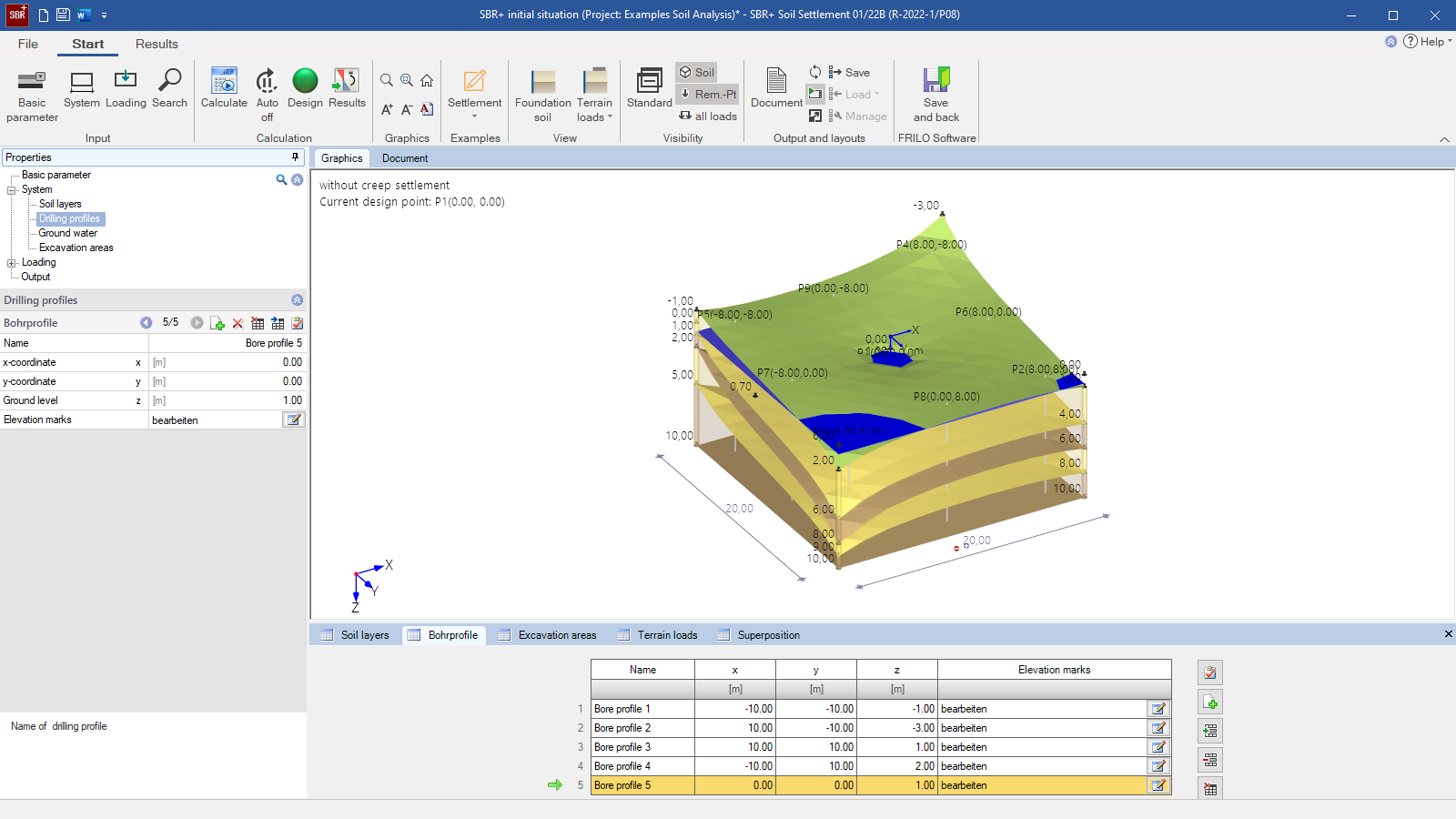
 SBR+ user interface
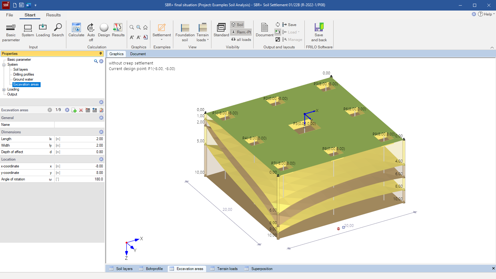
 - Excavation areas and design points for foundations
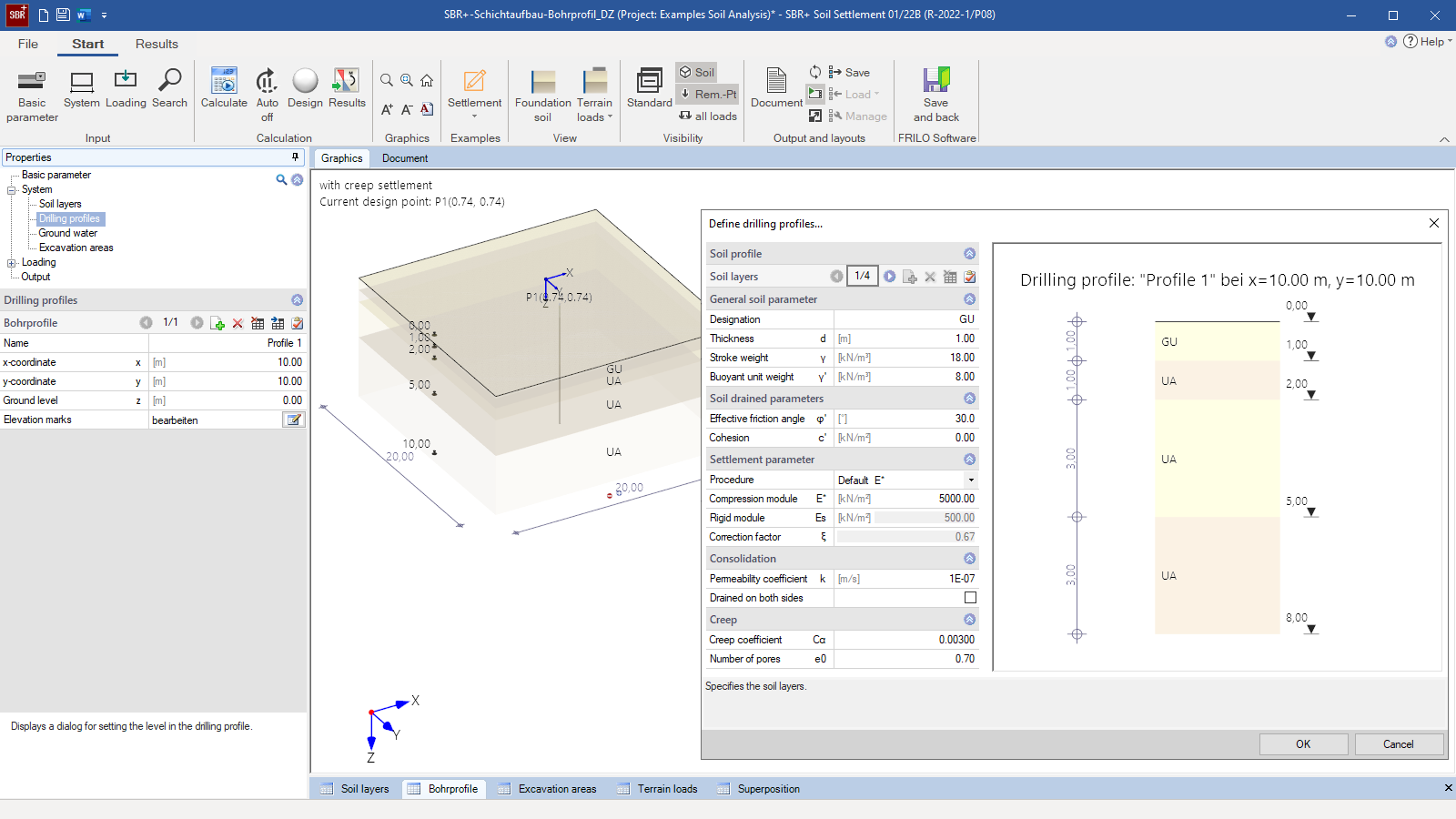
- Detail of the layer structure in the borehole profile
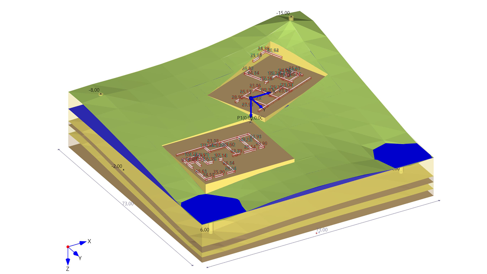
- Building loads imported from GEO
Soil Settlement
SBR+
The SBR+ program can be used to calculate the magnitude and the progression in time of the settlements and foundation tilting caused by volume or shape changes in the subsoil, which occur under perpendicular, static loading. Lifting due to relief by excavation can be calculated analogously. The shares from immediate and consolidation settlements are always calculated as a standard. Optionally you can add creep settlement. Via the definition of borehole profiles, a polygonal topographical model can be interpolated automatically.
Discover now more programs from the section Foundation Engineering!
SHOW MOREStructural system
Basic parameters
- Optional inclusion of creep settlement
- Automatic calculation of the limit settlement (abortion criterion)
System
- Dimensions and subdivisions of the model area
- Freely selectable number and position of the design points
Soil
- Any number of soil layers, with different thicknesses, if applicable
- Also, polygonal layer boundaries are possible
- Freely selectable soil parameters
- Special parameters for the calculation of settlements due to consolidation and creep
Ground surface
- Any polygonal three-dimensional ground surface can be defined
Borehole profiles
Via the definition of a freely selectable number of borehole profiles a polygonal ground surface and soil layer model can be interpolated automatically. For this interpolation, the user can assign any layer structure to each borehole profile.
Groundwater
Stagnant groundwater can optionally be taken into account. The buoyant unit weight of the water-saturated soil is automatically considered.
Excavation areas
Excavation relief (heave) due to foundation construction, construction pits, or excavations can optionally be taken into account by defining excavation areas.
Loads
The external loads can apply in the form of infinite perpendicular area loads, concentrated loads or limited block loads at any position at the level of the ground top edge.
Asymmetrical trapezoidal loads with different load ordinates at the respective edges can also be modelled at any position and with variable orientation.
By defining excavation areas, all loads can also be applied at a depth z below the ground top edge.
The number of ground-surface loads, their type of action, as well as the limit state and the design situation to be considered can be selected as desired.
Superposition
The load cases are automatically superimposed in accordance with the applicable superposition rules depending on the selected limit state and design situation.
Method of calculation
- Assumption of slack loads
- Indirect calculation of settlements with soil stresses in the isotropic elastic half-space
- Stresses are determined in accordance with Boussinesq, Steinbrenner, Tölke using stress influence coefficients
- Calculation of settlements through stress integration
- Calculation of the immediate settlement s0, the consolidation settlement s1 and, optionally, of the creep settlement s2
Document file formats
- Word
- Printer
Output
- The settlements can be put out for any number of freely selectable design points
- Output of a settlement trough over the entire model area
- Stress influence coefficients i per load case and per design point
- Settlement influence depth
- Stress-settlement diagram over the depth per design point
- Stress-settlement diagram according to the settlement shares s0, s1, s2, and stot per design point
- Time-settlement diagram per design point
Load import
- Isolated Foundation FD+
- Pad Foundation FDB+
- Mast Foundation FDM+
- Reinforced Raft Foundation FDR+
- Strip Foundation FDS+
- Pile Foundation Pfahl+
- Building Model GEO
Note on load import:
From the FD+ foundation program and the GEO Building Model, the decisive loads, including eccentricities, can be imported as block loads, either load case by load case or as superimposed loads.
For the calculation of base slabs, base pressures can be imported from GEO, which are simulated by a sufficient number of concentrated loads.
Geotechnical standards
- DIN EN 1997
- ÖNORM EN 1997
- PN EN 1997
- BS EN 1997
Support resources

News

FRILO launches version 2024-2 with powerful updates for structural analysis and design
Highlights include the optimised design of Schöck Isokörbe®, the advanced integration of DC foundation engineering programs into the FRILO environment and new RSX interfaces for detail verifications in steel construction.
Load determination for eight-floor perimeter block development with FRILO Building Model
Find out how the structural engineers at bauart Konstruktions GmbH determined the loads for an eight-floor perimeter block development in Frankfurt’s Europaviertel district using the GEO from FRILO.
Events
You may also be interested in these programs

