


-
 FDB+ user interface
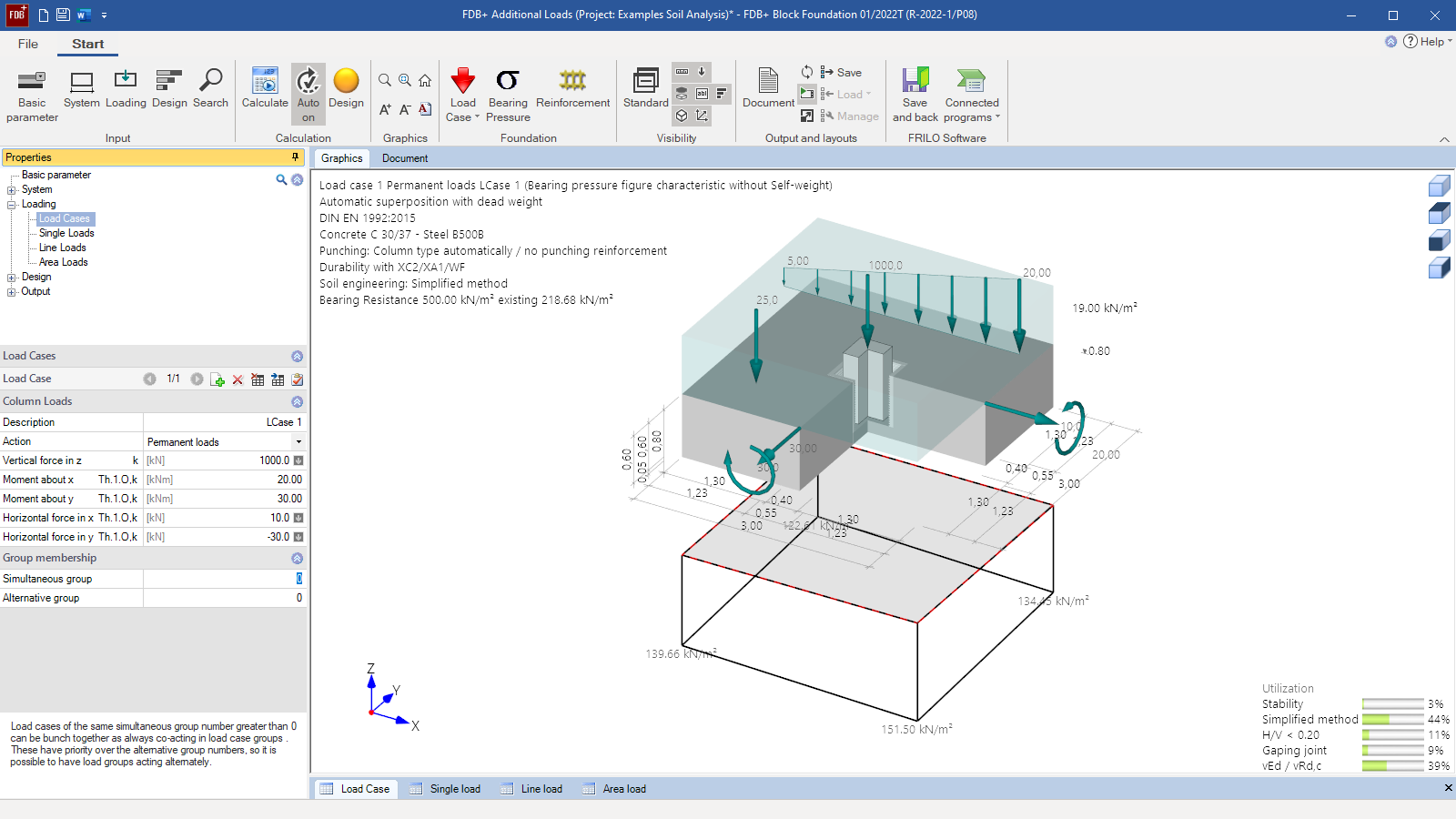
 - Column loads and additional loads
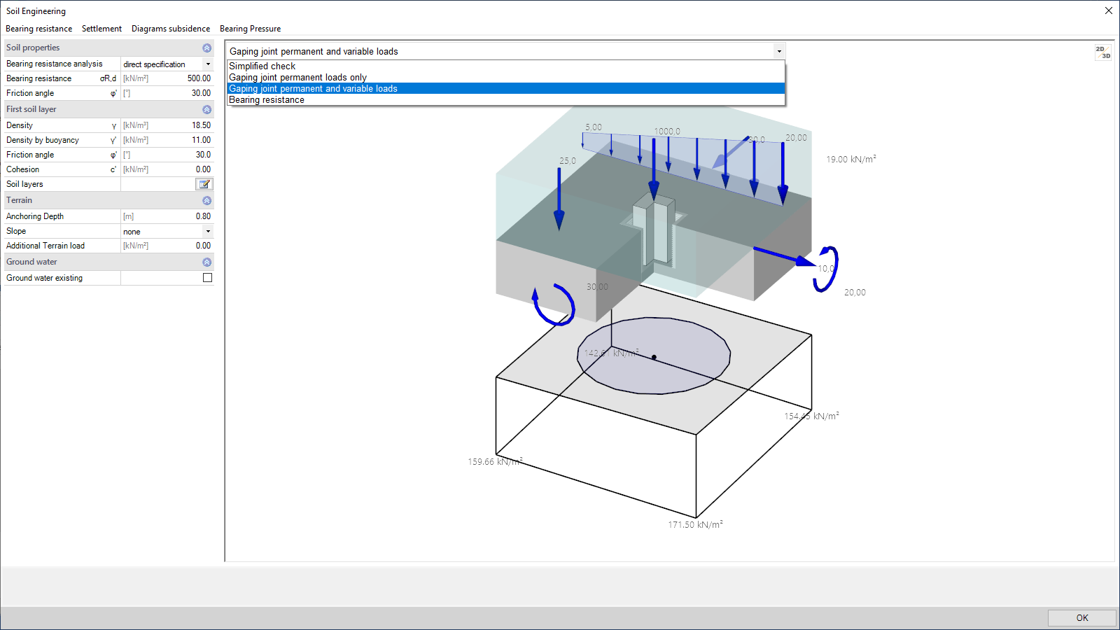
- Base pressure shape with second core range and neutral axis
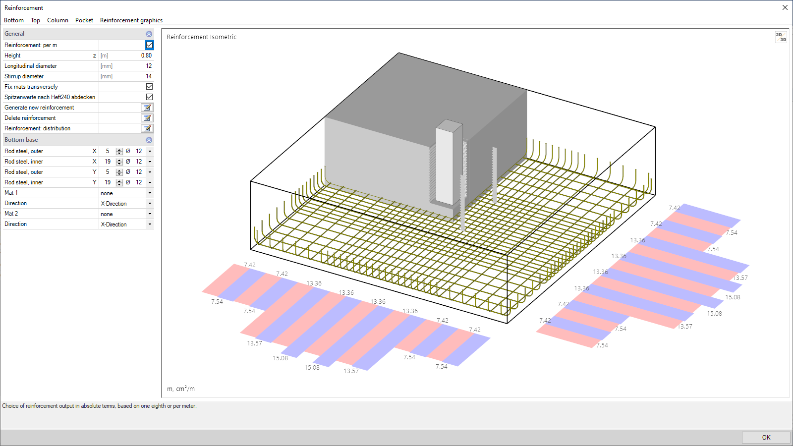
- Isometry of the arranged reinforcement
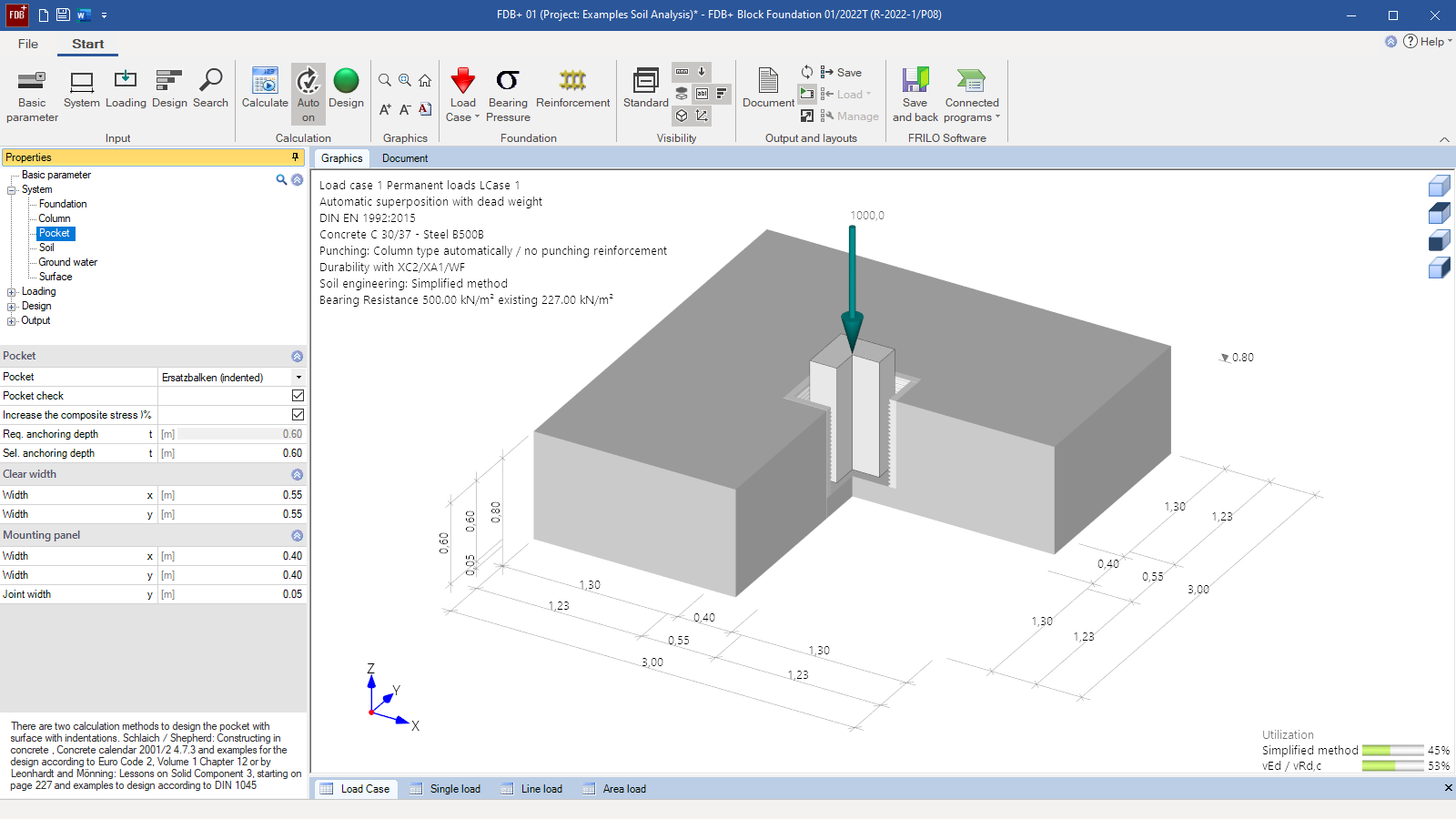
Pad Foundation
FDB+
FDB+ can be used to design block (pad) foundations in accordance with the method described in “Beispiele zur Bemessung nach Eurocode 2” (Examples for the Design as per Eurocode 2) published by “Deutscher Beton- und Bautechnik-Verein E.V. ” or in accordance with the method described in “Betonkalender 1988”, Part II, page 453. Block foundations are foundations in which a pocket is embedded. They are characterised by a toothed connection between the pocket wall and the column base. This connection has the same effect as if the column were fitted with a monolithic foundation.
Discover now more programs from the section Foundation!
SHOW MOREMaterial
- Reinforced concrete with selectable concrete qualities and steel grades
- Different materials for the foundation and the column
Structural system
- Square and rectangular foundations
- Optionally with eccentric column
- With interior base (block foundation)
- Toothed pocket surface (design in accordance with Leonhardt or Schlaich/Schäfer)
Soil:
- Any number of horizontal layers
- Freely selectable soil parameters
- Permissible base pressure resistance based on empirical values of DIN 1054
Ground surface:
- Horizontal or continuously ascending
- Any number of polygonal ground-surface sections
Groundwater:
- Stagnant groundwater can optionally be taken into account at any height level.
Loads
- Any column loads for biaxial loading, if applicable
- Vertical concentrated load V
- Horizontal concentrated load in the x- or y-direction (optionally applying to the top edge of the pocket or the foundation)
- Concentrated moments about the x-axis and the y-axis
- Any additional loads applying to the foundation as concentrated loads, line loads or area loads.
- Free assignment of loads to types of actions according to EC 0 as well as to concurrency and alternative groups.
- General separation of the definition of design loads and of characteristic loads with automatic load case combination
Reinforced concrete design (internal stability)
- Punching shear analysis with/without punching shear reinforcement
- Punching shear in the erecting state
- Bending design
- Shear force design
- Pocket design with strut-and-tie models
- Durability verification via exposure classes
- Consideration of different minimum reinforcement quantities
- The reinforcement dialog allows the definition of any reinforcement and arrangement
Pocket design
- On the equivalent beam (toothed)
- In accordance with Schlaich/ Schäfer (“Beispiele zur Bemessung nach Eurocode 2”, volume 1)
Geotechnical verifications (external stability)
- Simplified verification with base pressure resistances (either user-defined or based on tables of DIN 1054)
- Optional verifications using the accurate calculation method:
- Overturning
- Sliding
- Ground failure
- Optional settlement verification
- Serviceability via the verification of the gaping joint and torsion
Document file formats
- Word
- Printer
General
- Various output profiles available for selection (brief, detailed, user-defined)
- Selectable graphic scales and font sizes
- Detailed output of individual load cases
- Overview of the decisive load case combinations and their assignment to the design situation (persistent, transient, accidental and earthquake)
- Reinforcement sections can optionally be output in the form of a reinforcement plan
Reinforced concrete design
- Decisive base pressure distribution for the individual design calculations
- Detailed results in graphical and tabular form of the bending design in the x- and y-direction at the top and bottom of the foundation
- Graphical representation of the reinforcement distribution and, if applicable, staggered reinforcement quantities
- Detailed graphical and tabular representation of the results of the punching shear design
- Detailed output of the pocket design, if applicable
- Details on calculated lapping and anchorage lengths
Geotechnical verifications
- Tabular and graphical output of the selected decisive actions and base pressures for each selected geotechnical verification
- Verifications in the ULS (simplified with base pressure, overturning, sliding, ground failure)
- Verifications in the SLS (first and second core range, settlements, and torsion)
Transfer options
- Slabs by finite elements PLT
- Isolated Foundation FD+
- Mast Foundation FDM+
- Strip Foundation FDS+
- Reinforced Raft Foundation FDR+
- Ground Failure Analysis GBR+
- Beam on Elastic Foundation BEB+
- Soil Settlement SBR+
Geotechnical standards
- EN 1997
- DIN EN 1997
- ÖNORM EN 1997
- PN EN 1997
- NF EN 1997
- DIN 1054
- DIN 4017
- DIN 4019
- ÖNORM B 4435-2
Reinforced concrete
- EN 1992
- DIN EN 1992
- ÖNORM EN 1992
- PN EN 1992
- NF EN 1992
- BS EN 1992
- DIN 1045
- ÖNORM B 4700
Additional options
FDPro
With the additional option FDPro, the foundation programs FD+, FDB+, FDS+ and GBR+ can be extended to include:
- an earth pressure approach
- an inclined foundation base
- a seismic ground failure verification
- a ground failure – punching shear verification
- a bearing capacity calculation of the foundation soil with a table of design values of the base pressure resistance.
- a graphical output of the internal forces along the main axes
Note on the free 30-day demo
The additional option FDPro can also be tested for 30 days without a license. As soon as you call up a function from FDPro, you will be asked whether the function should start as a demo.
Find out more about the range of functions of the FDPro in the video.
FD-BEW
FD-BEW can be used to generate reinforcement graphics.
Support resources

News

FRILO launches version 2024-2 with powerful updates for structural analysis and design
Highlights include the optimised design of Schöck Isokörbe®, the advanced integration of DC foundation engineering programs into the FRILO environment and new RSX interfaces for detail verifications in steel construction.
Load determination for eight-floor perimeter block development with FRILO Building Model
Find out how the structural engineers at bauart Konstruktions GmbH determined the loads for an eight-floor perimeter block development in Frankfurt’s Europaviertel district using the GEO from FRILO.
Events
You may also be interested in these programs

