
-
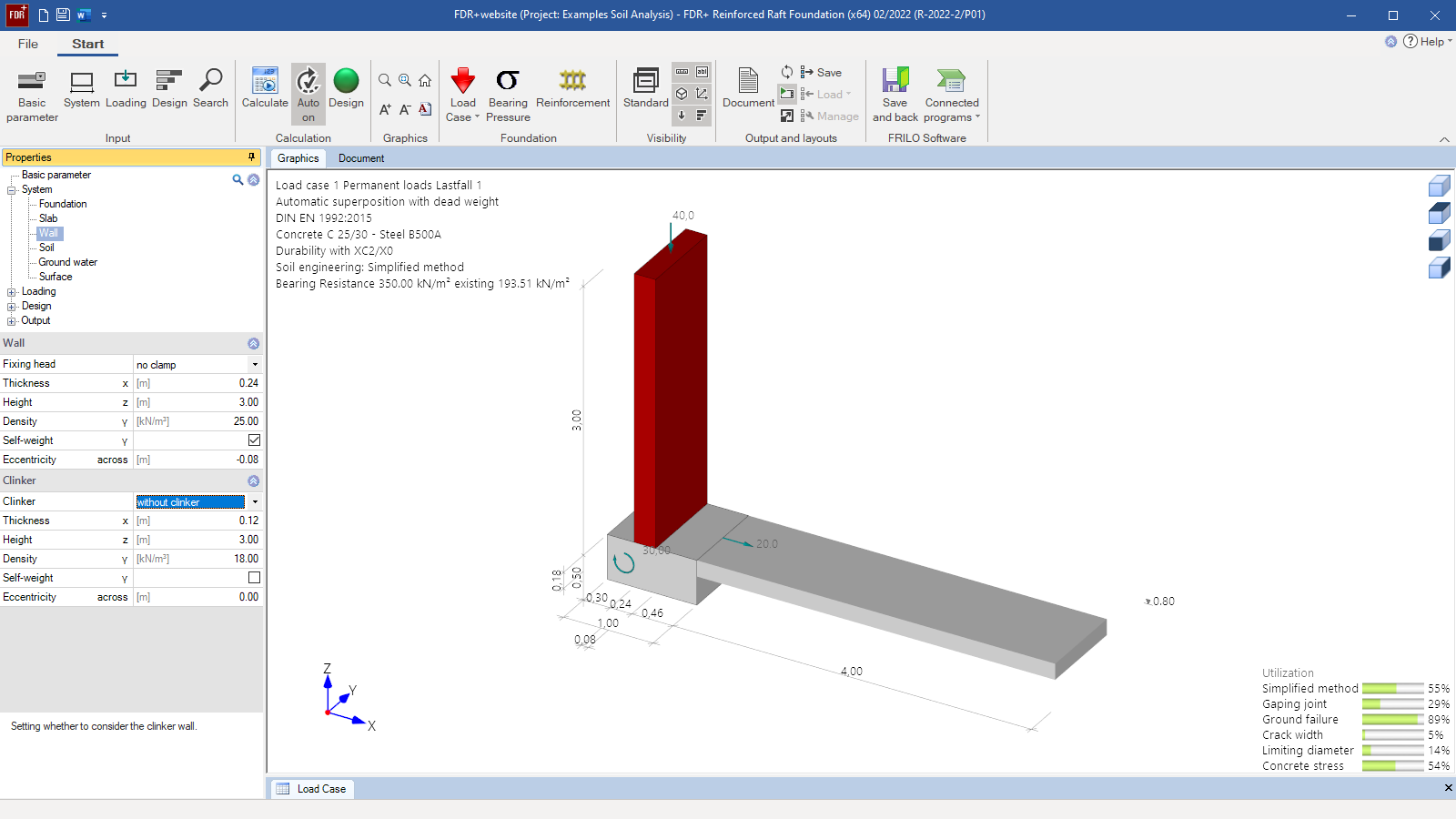 FDR+ user interface
 -
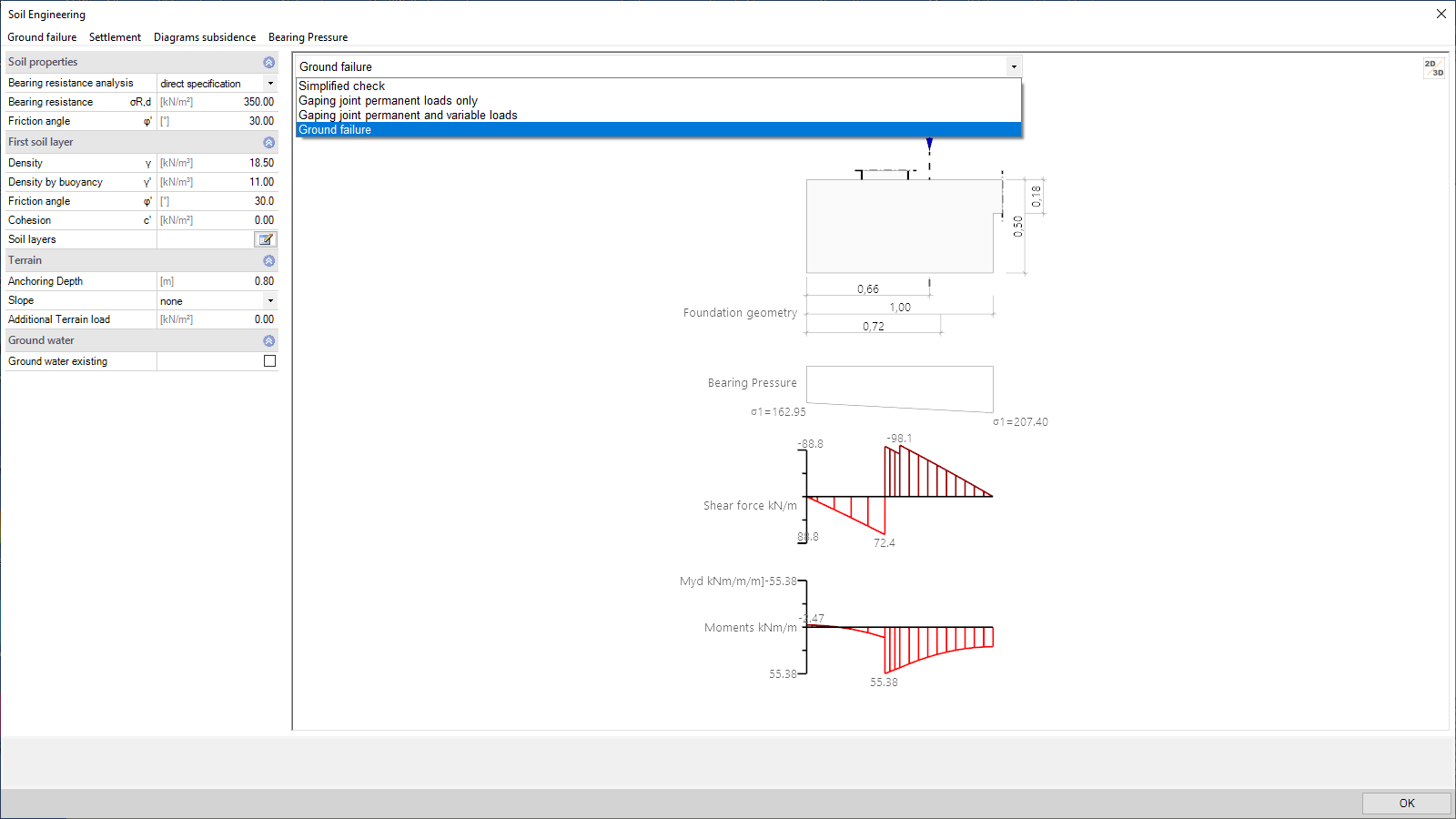 Base pressure shape with consideration of a centring moment from the slab
 -
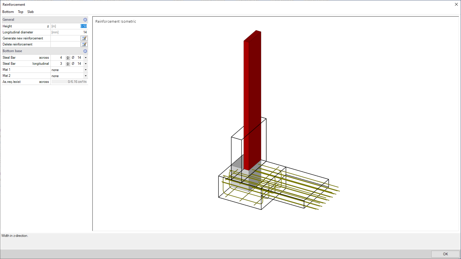 Isometry of the arranged reinforcement
Reinforced Raft Foundation
FDR+
The FDR+ program can be used to design eccentrically loaded boundary foundations that are connected to a reinforced concrete slab with a rigid joint. In the design, the centring moment, the centring tensile force and the soil pressure are determined with consideration of deformations. Optionally, a restraint in the wall can simultaneously be considered. The centring in the connected reinforced concrete slab is performed in accordance with J. Kayna (Bautechnik magazine 05/1969).
Discover now more programs from the section Foundation!
SHOW MOREMaterial
- Wall and facing optionally of masonry or reinforced concrete
- Reinforced concrete with selectable concrete qualities and steel grades
- Different materials for the foundation, the slab, and the wall
Structural system
- Square and rectangular foundations
- Eccentric arrangement of the wall
- Any geometry definable for the wall, the slab and the foundation to derive stiffness
- Pinned or flexurally rigid connection of the slab with user-defined stiffness factor
- Wall head with or without restraint or pinned support
Soil:
- Any number of horizontal layers
- Freely selectable soil parameters
- Permissible base pressure resistance based on empirical values of DIN 1054
Ground surface:
- Horizontal or continuously ascending
- Any number of polygonal ground-surface sections
Groundwater:
Stagnant groundwater can optionally be taken into account at any height level
Loads
- Any wall loads for uniaxial effects of actions:
- Vertical axial force Vz
- Horizontal concentrated loads in the x-direction
- Concentrated moments about the y-axis
- Optionally, additional loads can be defined in the foundation/slab connection if the connection is pinned.
- Optional inclusion of the self-weights of the wall, the facing, and the foundation independently of each other.
- Free assignment of loads to types of actions according to EC 0 as well as to concurrency and alternative groups.
- Automatic combination of loads for the calculation of the decisive design load case for each verification.
Reinforced concrete design (internal stability)
- Bending design at the foundation/slab connection
- Examination whether an unreinforced execution is possible
- Optional calculation of the connecting reinforcement in the upright reinforced concrete wall
- Centring in the flexurally rigid connected slab
- Simultaneous restraint in the wall and the slab is optionally selectable
- Durability verification via exposure classes
- Verification of the concrete compression stress and the steel tensile stress at the connection to the slab
- Crack width verification at the connection to the slab
- Consideration of different minimum reinforcement quantities
- The reinforcement dialog allows the definition of any reinforcement and arrangement
Geotechnical verifications (external stability)
- Simplified verification with base pressure resistances (either user-defined or taken from tables of DIN 1054)
- Optional verifications based on the accurate calculation method:
- Overturning
- Sliding
- Ground failure
- Optional settlement verification
- Serviceability via the verification of the gaping joint
- Calculation of deformation and torsion with consideration of the centring moments and the stiffness conditions
Document file formats
- Word
- Printer
General
- Various output profiles available for selection (brief, detailed, user-defined)
- Selectable graphic scales and font sizes
- Detailed output of individual load cases
- Overview of the decisive load case combinations and their assignment to the design situation (persistent, transient, accidental and earthquake)
Reinforced concrete design
- Decisive base pressure distribution for the different design calculations
- Bending design at the top and bottom of the foundation and detailed tabular output
- Details concerning internal forces, stiffness as well as centring forces and moments in accordance with Kanya
- Graphical representation of the reinforcement distribution
- Design of the connecting reinforcement, if applicable
- Details concerning the stress verification and the crack width verification
Geotechnical verifications
- Tabular and graphical output of the selected decisive actions and base pressures for each selected geotechnical verification
- Verifications in the ULS (simplified with base pressure, overturning, sliding, ground failure)
- Verifications in the SLS (first and second core range, settlements, and torsion)
Transfer options
- Slabs by Finite Elements PLT
- Isolated Foundation FD+
- Block Foundation FDB+
- Mast Foundation FDM+
- Strip Foundation FDS+
- Ground Failure Analysis GBR+
- Beam on Elastic Foundation BEB+
- Soil Settlement SBR+
Load import
- GEO Building Model
Geotechnical standards
- EN 1997
- DIN EN 1997
- ÖNORM EN 1997
- PN EN 1997
- NF EN 1997
- DIN 1054
- DIN 4017
- DIN 4019
- ÖNORM B 4435-2
Reinforced concrete
- EN 1992
- DIN EN 1992
- ÖNORM EN 1992
- PN EN 1992
- NF EN 1992
- BS EN 1992
- DIN 1045
Support resources
News

FRILO launches version 2024-2 with powerful updates for structural analysis and design
Highlights include the optimised design of Schöck Isokörbe®, the advanced integration of DC foundation engineering programs into the FRILO environment and new RSX interfaces for detail verifications in steel construction.

Load determination for eight-floor perimeter block development with FRILO Building Model
Find out how the structural engineers at bauart Konstruktions GmbH determined the loads for an eight-floor perimeter block development in Frankfurt’s Europaviertel district using the GEO from FRILO.