
-
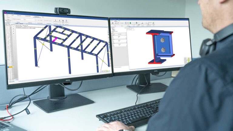
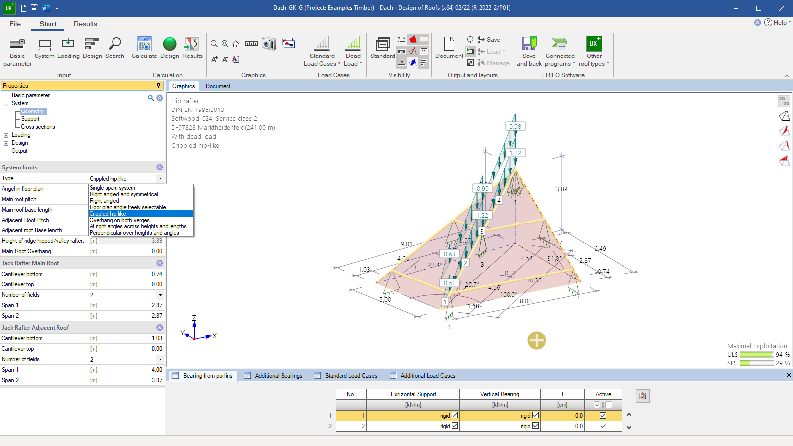 User interface with hip rafter
 -
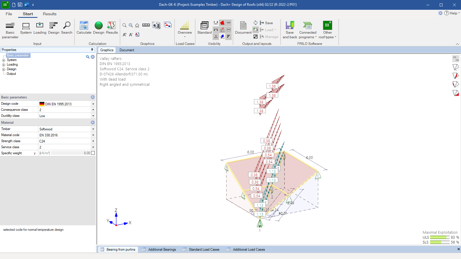 User interface with valley rafter
 -
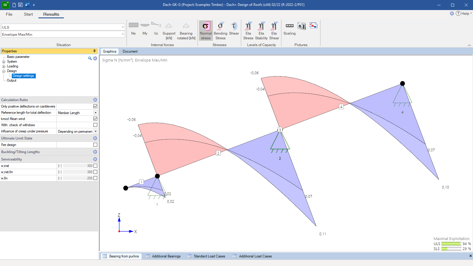 Graphical representation of the results
 -
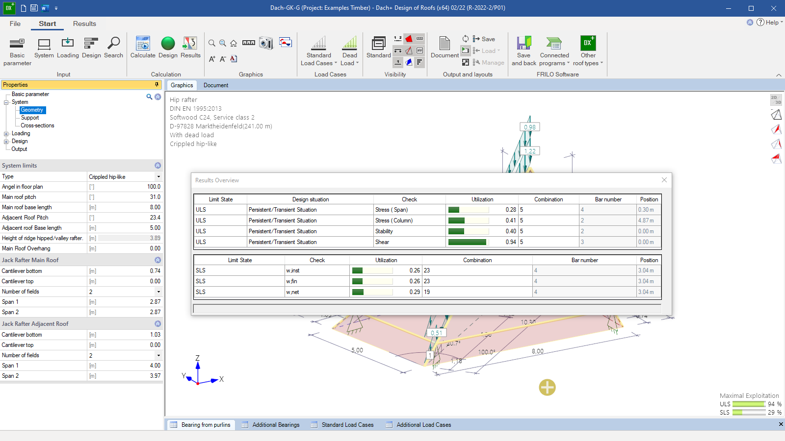 Verifications
 -
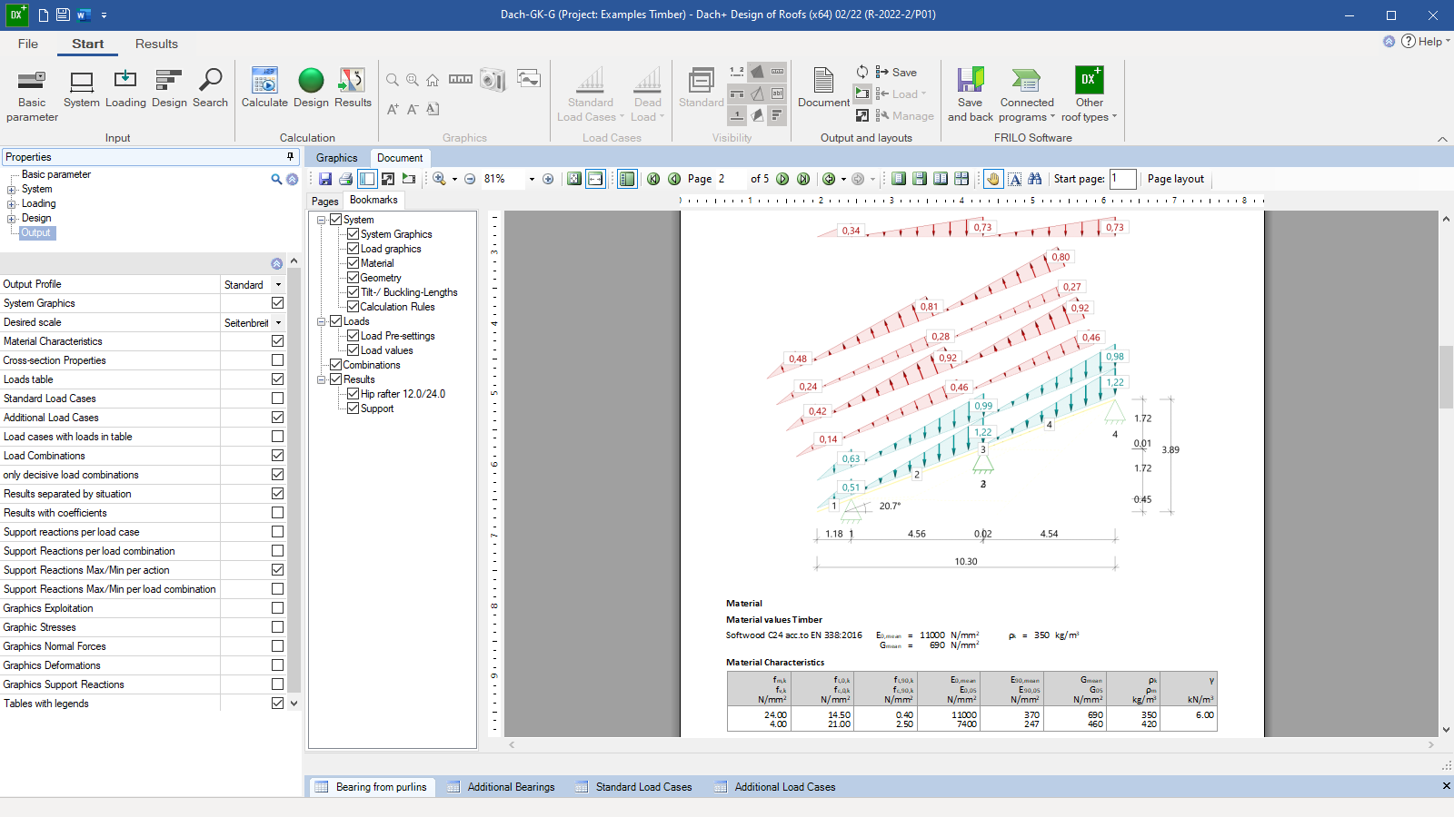 Output document with graphic
Hip-/Valley Rafter
DGK+
Verification of single-span and multi-span hip rafters or valley rafters with freely selectable angles for the floor plan and the roof pitches of the main and secondary roofs. Roof projections are possible.
Discover now more programs from the section Roof!
SHOW MOREMaterial
- Softwood
- Hardwood
- Glulam
Structural system
- The hip or valley rafter is a straight continuous beam under bending stress with the same cross-section over several spans without intermediate joints
- The roof pitches of the main and secondary roofs can be different
- The floor plan can have other angles than 90°
- The rafter can be supported by purlins that influence the loading situation and by additional supports that do not influence the loading situation
- The positions of the purlins can be different for the main and secondary roofs
- The supports can be defined as being rigid or elastic
- Simplified reduction of the cross-section by the depth of the birdsmouth
- Cantilevers on top/bottom
- Dormers are possible
- Various roof types are available for selection and provide for an effective entry of the geometry
Loads
- Automatic generation of the loads from self-weight, snow and wind
- Additional user-defined loads as uniformly distributed loads, concentrated loads or trapezoidal loads
- Accidental snow load is optionally available
- To reduce the computing time for more extensive systems, various settings are available for the grouping of load cases and load combinations
Design settings
Optionally selectable:
- Seismic load combinations
- Hot design
- As a standard option, only positive deflections are verified on the cantilever (on short cantilevers, the negative deflection is often decisive in terms of calculation, but this is not always desired)
Effective length for buckling and lateral buckling separately for the cold and hot design:
- Default setting: calculation of the effective length for buckling from the eigenvalue solution of the plane system. Assumption of continuous lateral support with limitation of the maximum effective length for buckling in the rafter plane to 0.9 times the component length
- Alternatively, setting the effective length to the length of the member, the component or a default value
Document file formats
- Word
- Printer
Output
- User-defined output with various setting options for tables and graphics
- Result graphics with internal forces, stresses or displacements can be specifically transferred to the output document using the camera button
- Support reactions are optionally put out for each load case, each action or as min/max values
Transfer options
- System transfer to the other Roof programs
- System transfer to the RSX Frame program
- Transfer of support reactions to the Timber Column program HO1+
- Direct interface to the CAD programs from SEMA
Timber construction
- DIN EN 1995
- ÖNORM EN 1995
- NTC EN 1995
- BS EN 1995
- PN EN 1995
- EN 1995
News
FRILO launches version 2024-2 with powerful updates for structural analysis and design
Highlights include the optimised design of Schöck Isokörbe®, the advanced integration of DC foundation engineering programs into the FRILO environment and new RSX interfaces for detail verifications in steel construction.
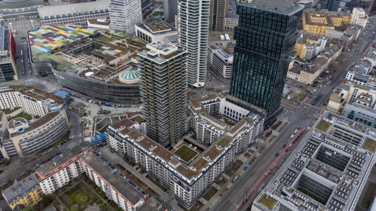
Load determination for eight-floor perimeter block development with FRILO Building Model
Find out how the structural engineers at bauart Konstruktions GmbH determined the loads for an eight-floor perimeter block development in Frankfurt’s Europaviertel district using the GEO from FRILO.