
Pit Wall
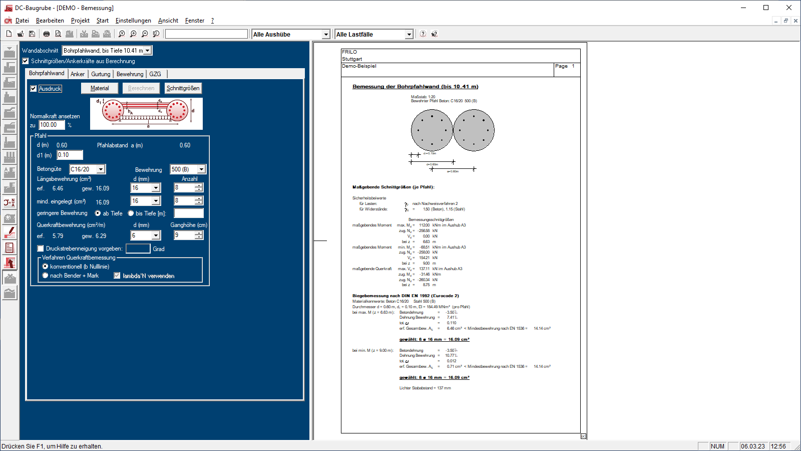
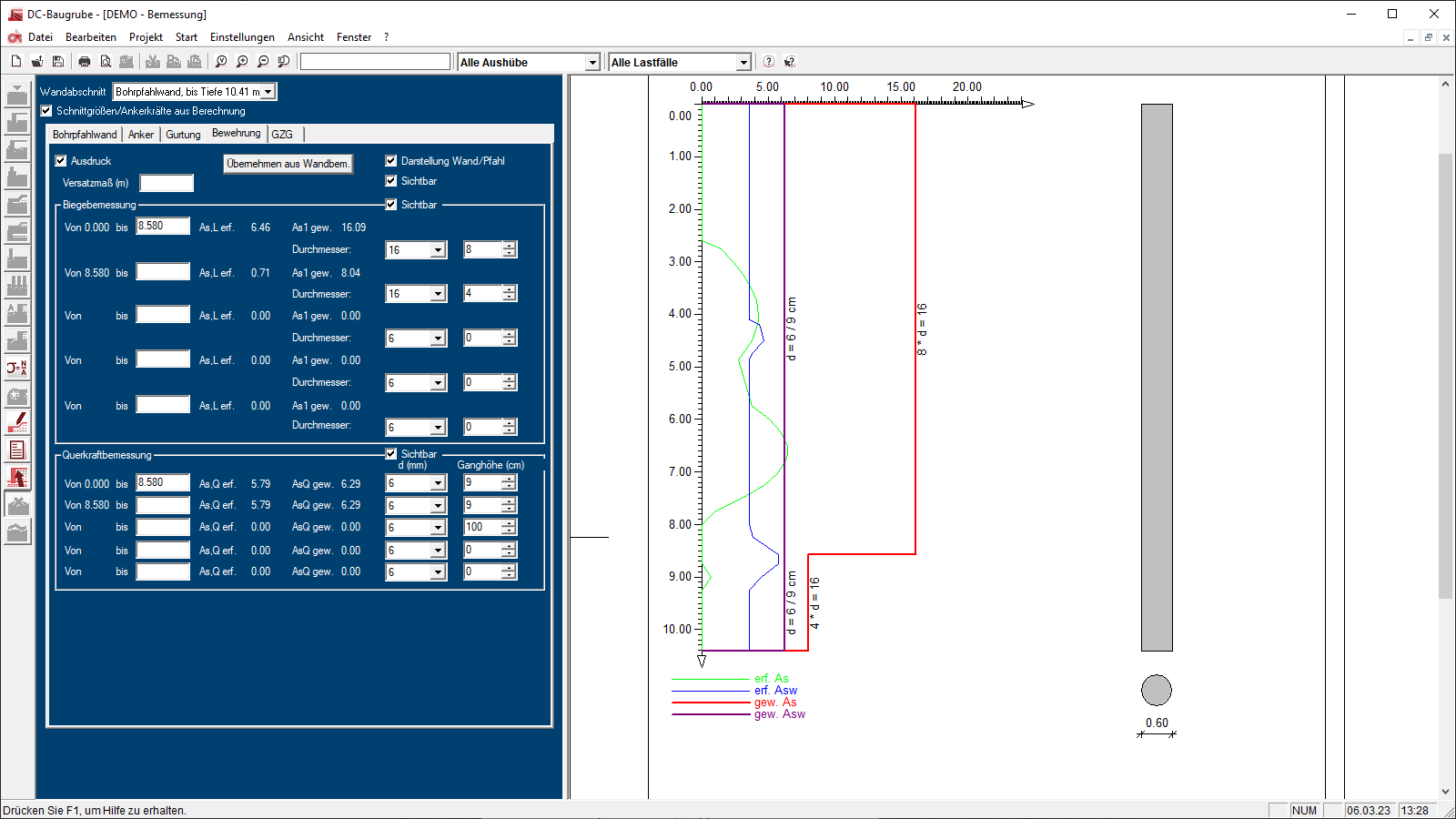
The “Pit Wall” module can be used to model construction pits in 2d and 3d. Anchor positions and booms on the lining walls can be displayed, as can all relevant cables and pipelines in the immediate vicinity of the construction pit. In addition, users can comprehensively analyze, design, and reinforce the modeled construction pit walls like bore pile walls, diaphragm walls, sheet pile walls, girder plank walls, and mixed in place (MIP) walls.
Also available in FRILO Geotechnic Ultimate
Core capabilities
This feature is used to model construction pits. Thanks to extensive CAD functions, construction pits can be drawn in detail in a 2d plan or modeled in 3d. All calculation sections can be edited and managed in a comprehensive plan. Graphical displays of the results can be integrated into the plan. The program has interfaces for data transfer to other FRILO analysis programs, in which, for example, excavations are defined and analysis and design are performed.
Material
- Selection of predefined sheet piling types and beam sections (HE-A etc.)
Structural system
- Drawings with extensive CAD functions
- Assignment of depth information and lining types to lines:
- Bore pile walls
- Diaphragm walls
- Sheet pile walls
- Girder plank walls
- Mixed in place (MIP) walls
- Underpinnings,
- Nail walls
- Embankments
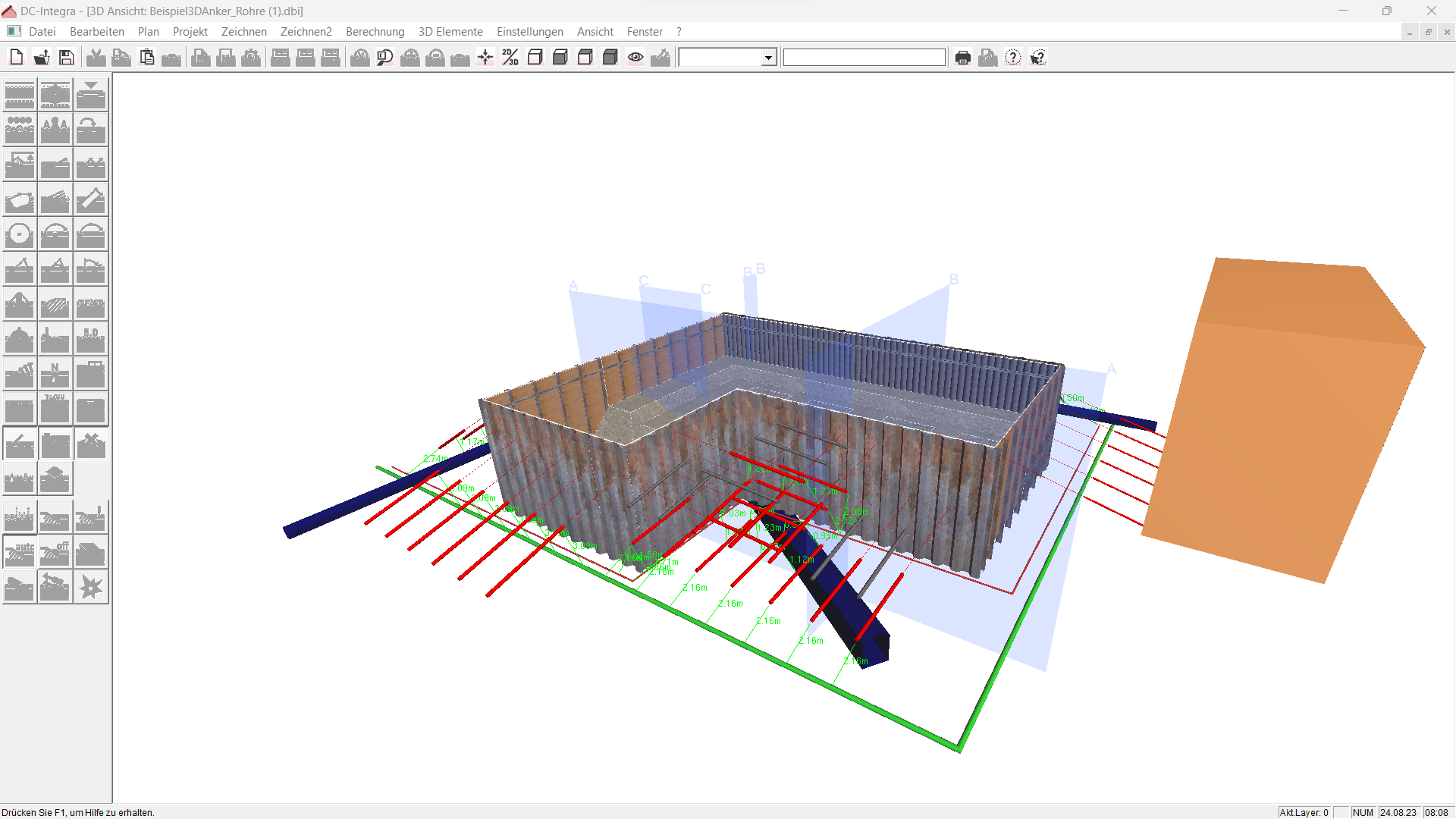
- Comprehensive 3d model with an accurate representation of all wall types, slopes and soil layers
- Length adjustment for sheet piling profiles to support correct corner formation
- Special corner formations for girder plank walls:
- U girder on I girder
- I girder in the angle bisecting line
- Automatic generation of the slope intersections between different depth sections
- Any views by rotating and moving the model
- Creation of 3d images of complex construction pit situations with photorealistic representation
- For the accurate modeling of the structural system (incl. the ground plan), it is possible to import DXF graphics and image files as a background as well as ground plans from “Vibro-Compaction” program
Pipeworks
- Overview of the position of all relevent cables and pipelines in the immediate vicinity of the construction pit using 3d modeling and visualization
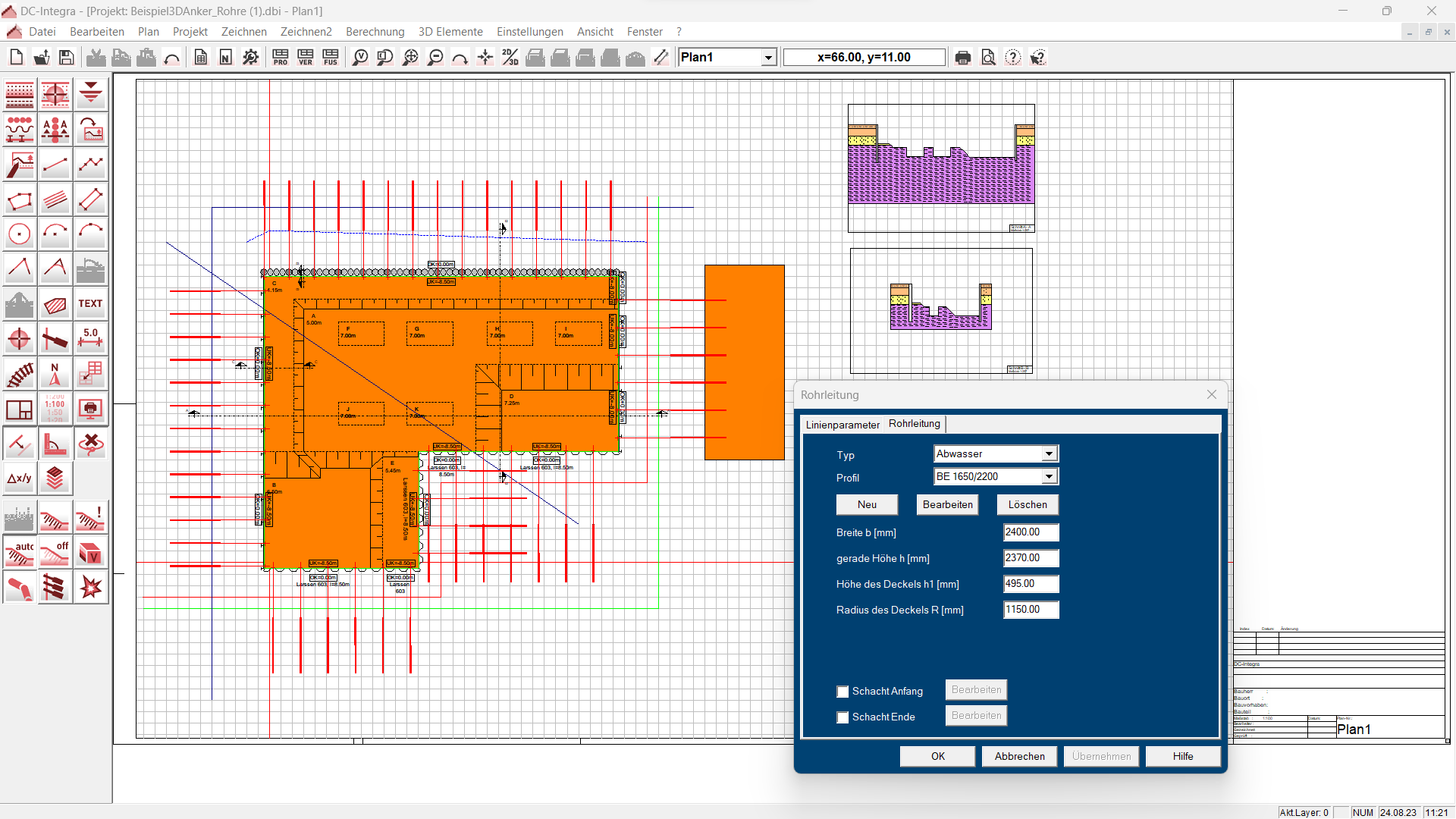
- Representation of different types of utility lines: wastewater, water supply, gas supply, power supply, district heating, cable channels
- Different cross-sections: duct profiles, circular profiles, rectangular profiles, various dimensions of (egg-shaped) duct profiles are freely definable
- Optional connection of the pipelines to shafts
- Position of pipes via specifications with coordinates or gradient
- Elevation reference by specifying a reference height or a height above MSL
Anchor
- 3d modeling and representation of anchor positions and booms on the lining walls
- Specifications for anchors: depth, length and inclination, sweep or spread, if required
- Specifications for grouted anchor bodies: lengths and diameter
- Consideration of the specified minimum distances between the steel tendon or the grouted anchor body and other anchors, utility lines or buildings for the collision check
- Dimensioning of the critical distances
- Modification of anchor depth and/or inclination at critical points
Soil
- Management of layer information and groundwater
- Variable input via bore points with interpolation of the stratification
Ground surface
- Horizontal and inclined ground surface, automatic interpolation of the height above MSL with an assignment to the layer
- Slopes inside the construction pit are possible
Output profile
- Definition of the calculation sections via any number of section lines
- Update function for changes in the calculated section
- Management of all sections in one drawing
- Integration of the result graphics into the drawing
- Creation of drawings in the standard sizes DIN A4 to DIN A0 and in freely definable sizes
File formats
- Printer
Reinforced concrete
- EN 1992
- DIN EN 1992
- ÖNORM B 1992
- NF EN 1992
- BS EN 1992
- UNI EN 1992
- DIN 1045
- SIA 262
- ÖNORM B 4700
- BS 8110
Steel
- EN 1993
- DIN EN 1993
- ÖNORM B 1993
- NF EN 1993
- BS EN 1993
- UNI EN 1993
- SIA 263
- BS 5950
Soil stratification
- Automatic iteration of a 3d soil layer model from layer information of defined exploratory boreholes
- Automatic iteration of a ground surface model from point clouds or exploratory boreholes
Geometry
- Slope geometry and intersection lines of slopes
- Automatic wall length analysis based on the ground surface profile
- Automatic adjustment of the floor plan to multiples of the lining wall profiles (e.g., sheet pile width)
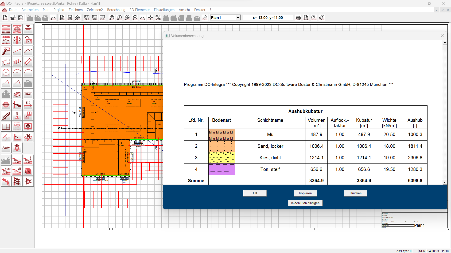
Excavation volume
- Volume and mass are determined in relation to the respective layer, so that the information is available separately for other purposes (e. g. contaminated sites).
- Consideration of the specified loosening factor of the respective soil layer
- Determination of the excavation mass via the specific weight of the soil
- Output of the masses in a table
Collision check
- Color coding of all objects at risk of collision
- Specification of the relevant distance of all objects in the collision check
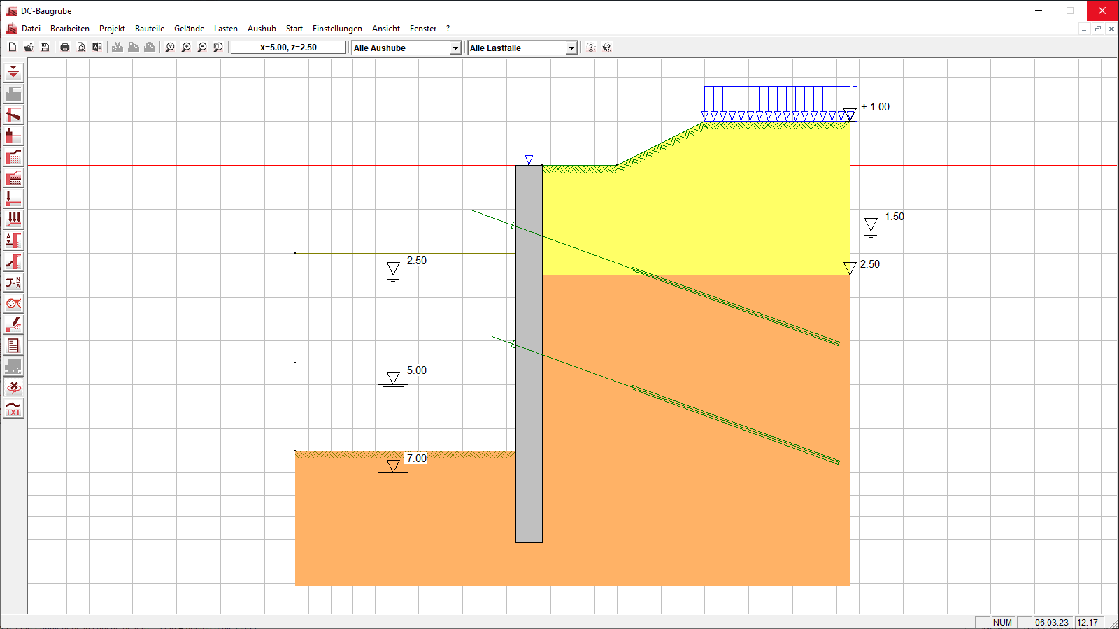
Sections
- Analysis and output of section geometries taking into account the construction pit and the surrounding soil layers
Support resources
News

Corporate headquarters as reinforced concrete skeleton structure
With the construction of a new corporate headquarters, Heidelberg Materials has demonstrated the remarkable range of reinforced concrete as an attractive building material. FRILO and Allplan were used by the structural engineers.
FRILO launches version 2024-2 with powerful updates for structural analysis and design
Highlights include the optimised design of Schöck Isokörbe®, the advanced integration of DC foundation engineering programs into the FRILO environment and new RSX interfaces for detail verifications in steel construction.