
Prestressed Reinforced Concrete Girder
The “Prestressed Reinforced Concrete Girder” program is used to analyze reinforced concrete beams and pre-tensioned girders (long-line method). The software performs all required verifications of the load-bearing capacity (also for the accidental and earthquake design situations) as well as serviceability verifications. The untensioned and pre-tensioned reinforcement including its prestressing in the prestressing bed is specified. The user is supported by a pre-design during the initial input and a guide if verifications are not fulfilled.
Only available in FRILO Professional und FRILO Ultimate
Core capabilities
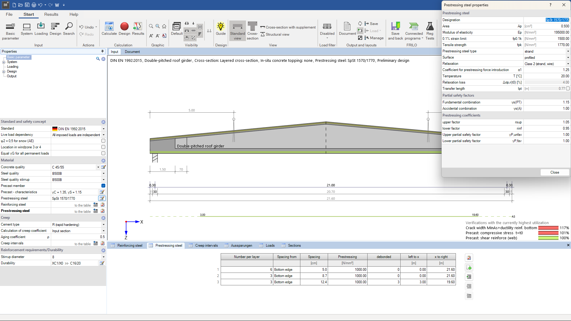
Material
- Concrete grades specified in the standard from C12/15 to C100/115 for the girder and C12/15 to C100/115 for the cast-in-place concrete supplement
- Optional definition of a gradual application of the pre-tensioning force
- Optional definition of reduced material safety coefficients for pre-cast components
- Optional consideration of a thermal treatment
- Increased compressive strength of the young concrete at the time of tensioning force application is possible
Structural system
- The user can calculate the girder in the final state and during its storage, as a single-span girder or as a cantilevered single-span girder
- For the erecting state, the user can examine a separate structural system aligned to the location of the suspension points
- The structural systems that result from auxiliary supports installed during the casting of the cast-in-place concrete complements are automatically taken into account in the calculation of the cross-sections
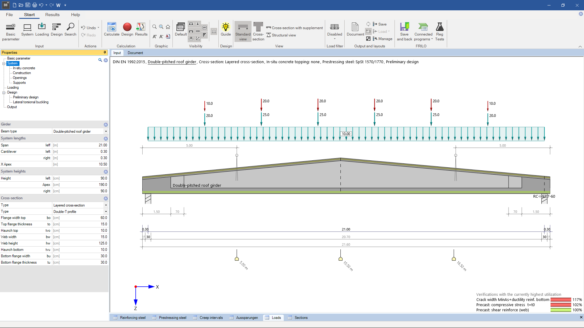
Girder types
- Girder with parallel flanges
- Symmetrical and asymmetrical girders with saddle or groove
- Single-pitch roof girder
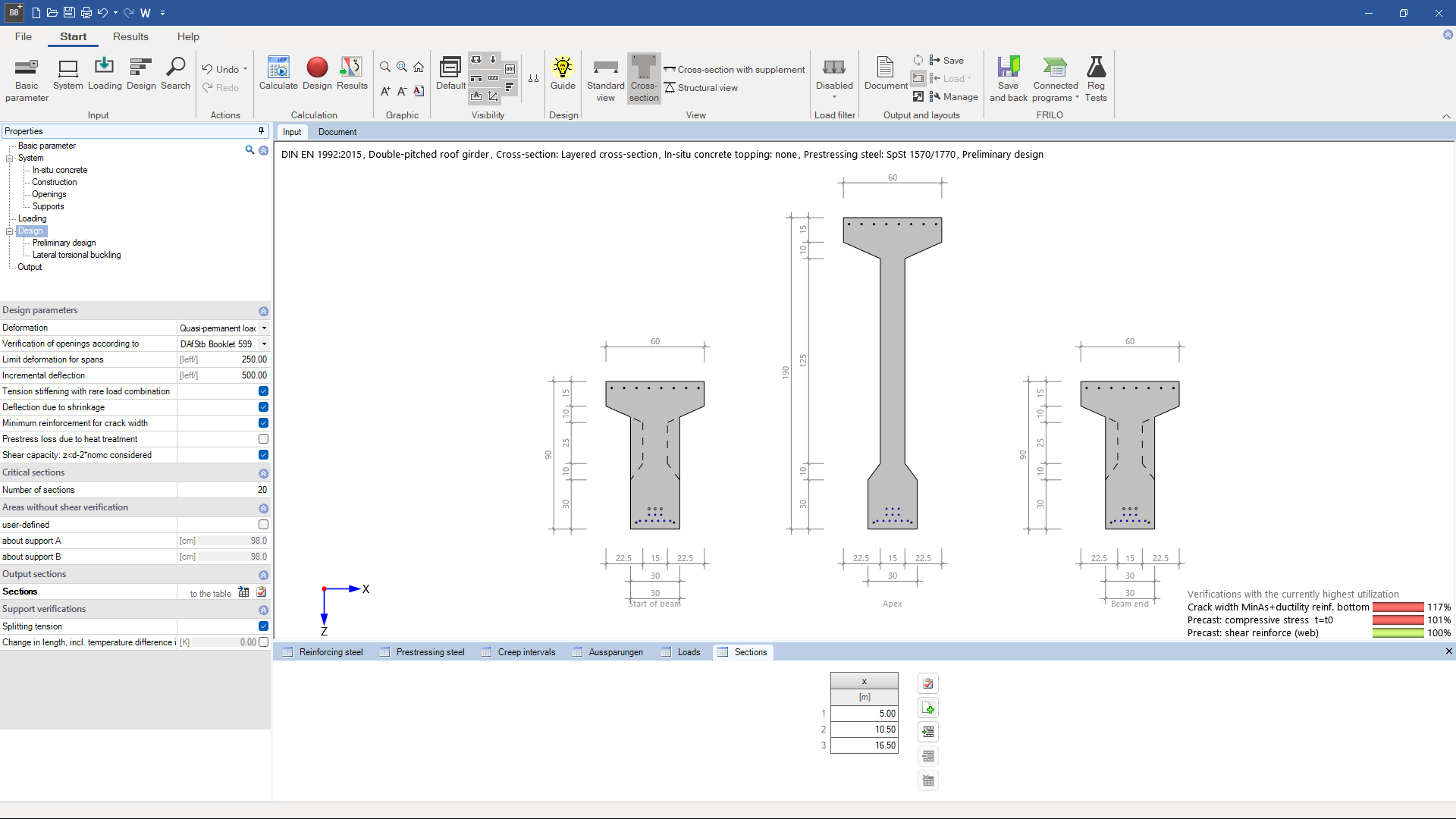
Shapes of cross-sections
- Rectangular cross-sections
- T-beams
- Two-webbed T-beams
- Layered cross-section
Optional cross-section complement
- Solid slab
- Solid slab with pre-fabricated formwork
- Complement with additional layer
Optional cut-outs
- circular
- rectangular
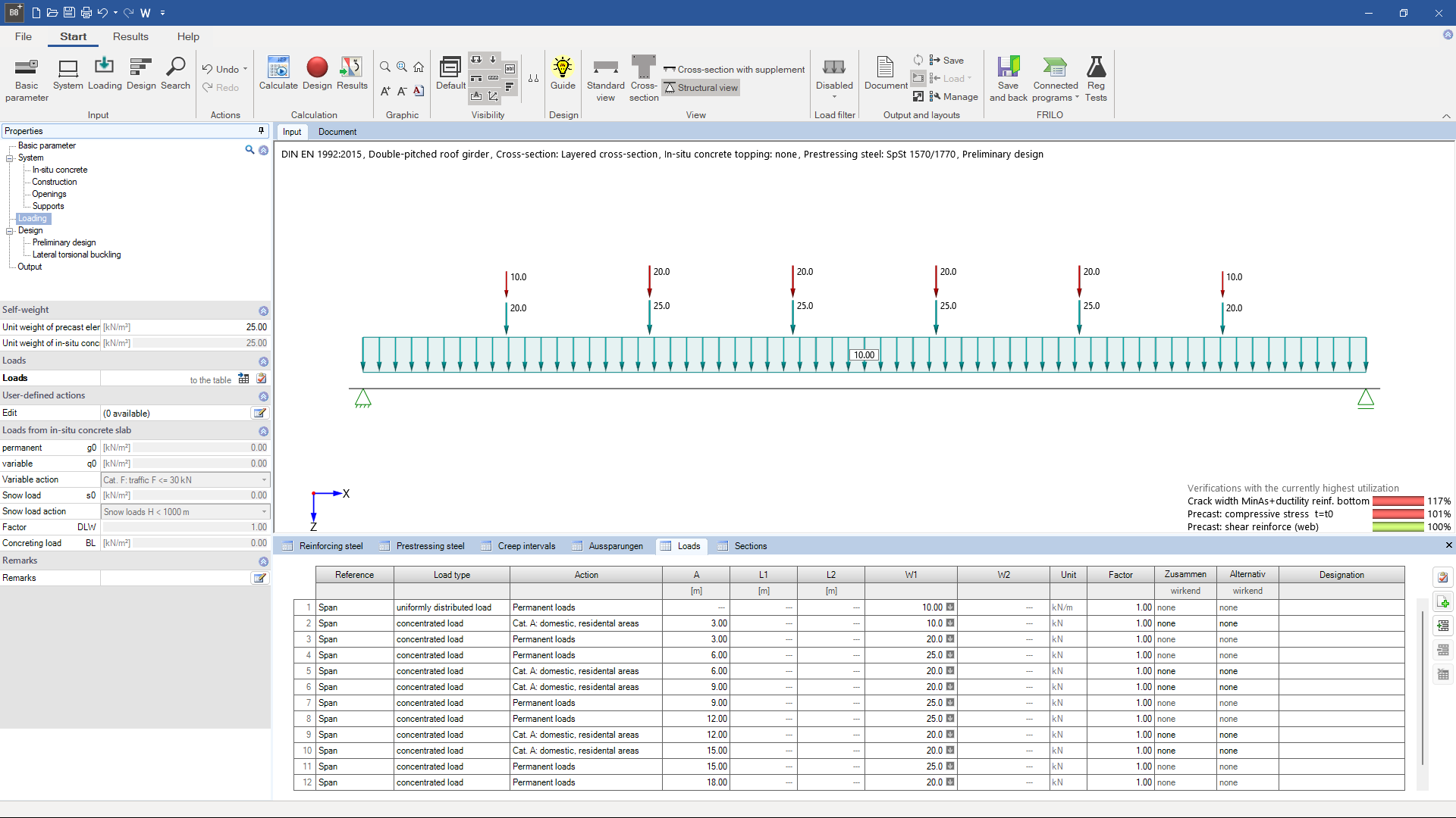
Loads
- Uniformly distributed linear loads
- Concentrated loads and moments
- Trapezoidal loads and triangular loads
- Loads can apply simultaneously or alternatively
Ultimate limit state
- Bending with longitudinal force (including resisting tensile force coverage)
- Shear resistance, for cast-in-place complements including the bearing capacity of the joints
- Lateral buckling in the installed state and in the erecting state (method by Stiglat and Mann)
- Determination of the tensile splitting reinforcement
- Anchoring of the prestressing reinforcement
- Dimensioning of cut-outs according to DAfStb booklets 399 and 599
Serviceability limit state
- Concrete stresses, steel stresses (prestressed steel, reinforcing steel)
- Crack width (loading, minimum reinforcement), verification of the decompression, if required
- Deflection for a selectable load combination of the SLS with consideration of state II including tension stiffening and shrinkage
- Changes in length due to temperature, creep and shrinkage
Reinforcement
- Multi-layer pre-tensioned reinforcement with insulation, if applicable
- Multi-layer untensioned reinforcement
- It is assumed that the reinforcement runs in a straight line in parallel to the upper or lower flange.
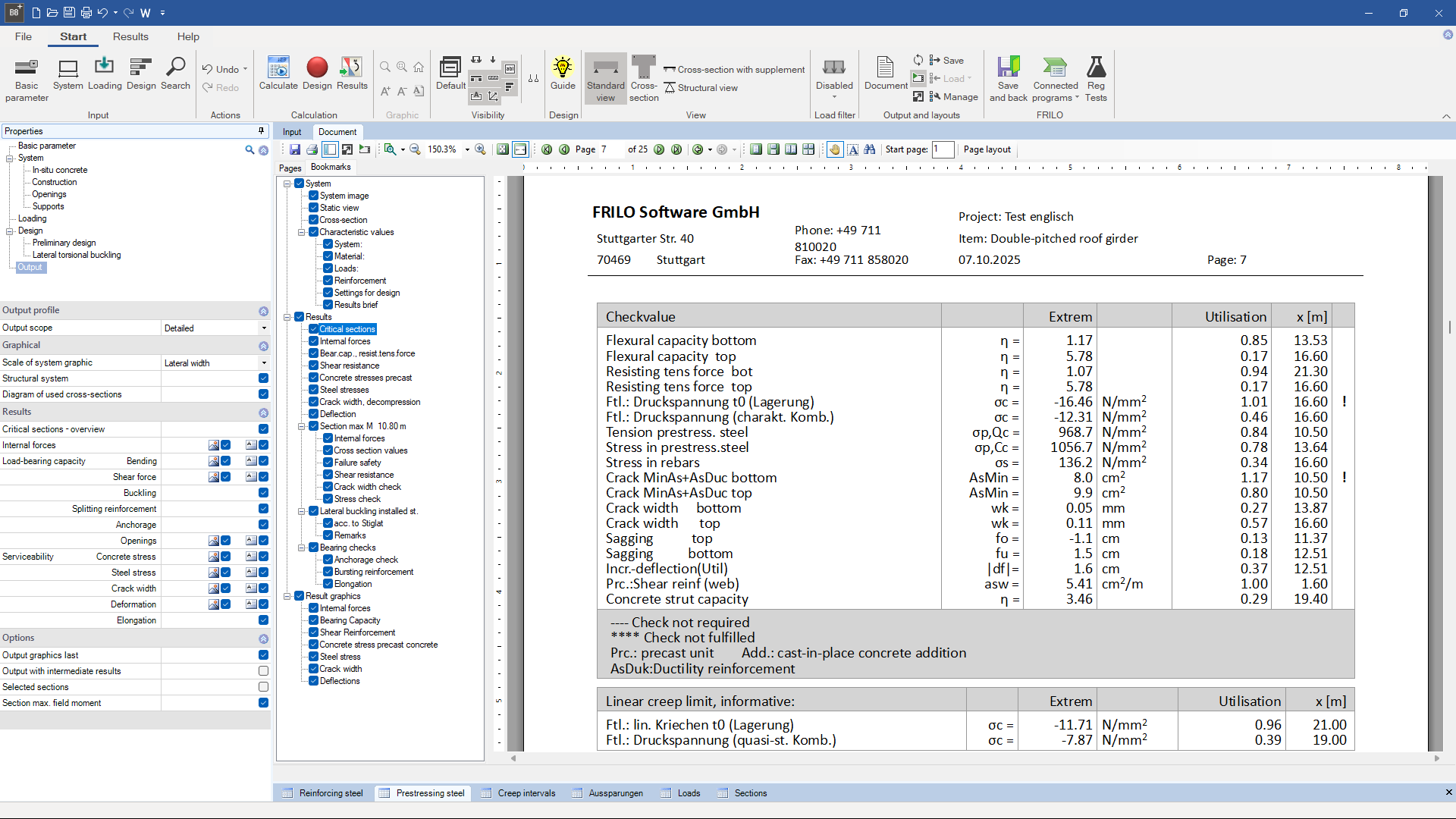
Output profile
- Output of various verifications in tabular or graphical form and with intermediate results is possible
- Verifications in the ultimate limit state
- Verifications in the serviceability limit state
File formats
- Word
- Printer
Import options
- ASCII file
Export options
- Word
- FRILO XML
Reinforced concrete
- EN 1992
- DIN EN 1992
- ÖNORM B 1992
- PN EN 1992
- BS EN 1992
- DIN 1045-1
Support resources
News

Corporate headquarters as reinforced concrete skeleton structure
With the construction of a new corporate headquarters, Heidelberg Materials has demonstrated the remarkable range of reinforced concrete as an attractive building material. FRILO and Allplan were used by the structural engineers.

FRILO launches version 2024-2 with powerful updates for structural analysis and design
Highlights include the optimised design of Schöck Isokörbe®, the advanced integration of DC foundation engineering programs into the FRILO environment and new RSX interfaces for detail verifications in steel construction.