
Verification of Reinforced Concrete Cross-Sections
With the “Verification of Reinforced Concrete Cross-Sections” program, the design of reinforced concrete cross-sections can be performed. Cross-sections for single- and double-axis bending with longitudinal force, as well as for shear force and torsion can be designed. Furthermore, users can perform crack width verifications, fire protection verifications and stress analyses or determine the effective stiffness.
Only available in FRILO Professional und FRILO Ultimate
Core capabilities
Material
- Concrete of the strength classes C12/15 to C100/115
- Lightweight concrete of the strength classes LC 12/13 to LC 80/88
- Concrete and reinforcing steel with user defined parameters
- Reinforcing steel of the steel grades B500A, B500B and BSt 420 S(A) in combination with the German NA (corresponding qualities for all other available NAs)
- Historical materials according to DAfStb Issue 616 (currently only in old B2)
- The material factors are adjusted according to the design situation (permanent/temporary, accidental, earthquake), type of concrete (normal weight, lightweight), and for cast-in-place or precast components
In addition to standard reinforcing steel, reinforcements made of glass fiber-reinforced plastic (Schöck Combar®) can also be used in accordance with DIN EN 1992. High-strength reinforcement or stainless steel reinforcement can be taken into account using the free material definition.
Structural System
- Rectangular cross-section, uniaxial and biaxial
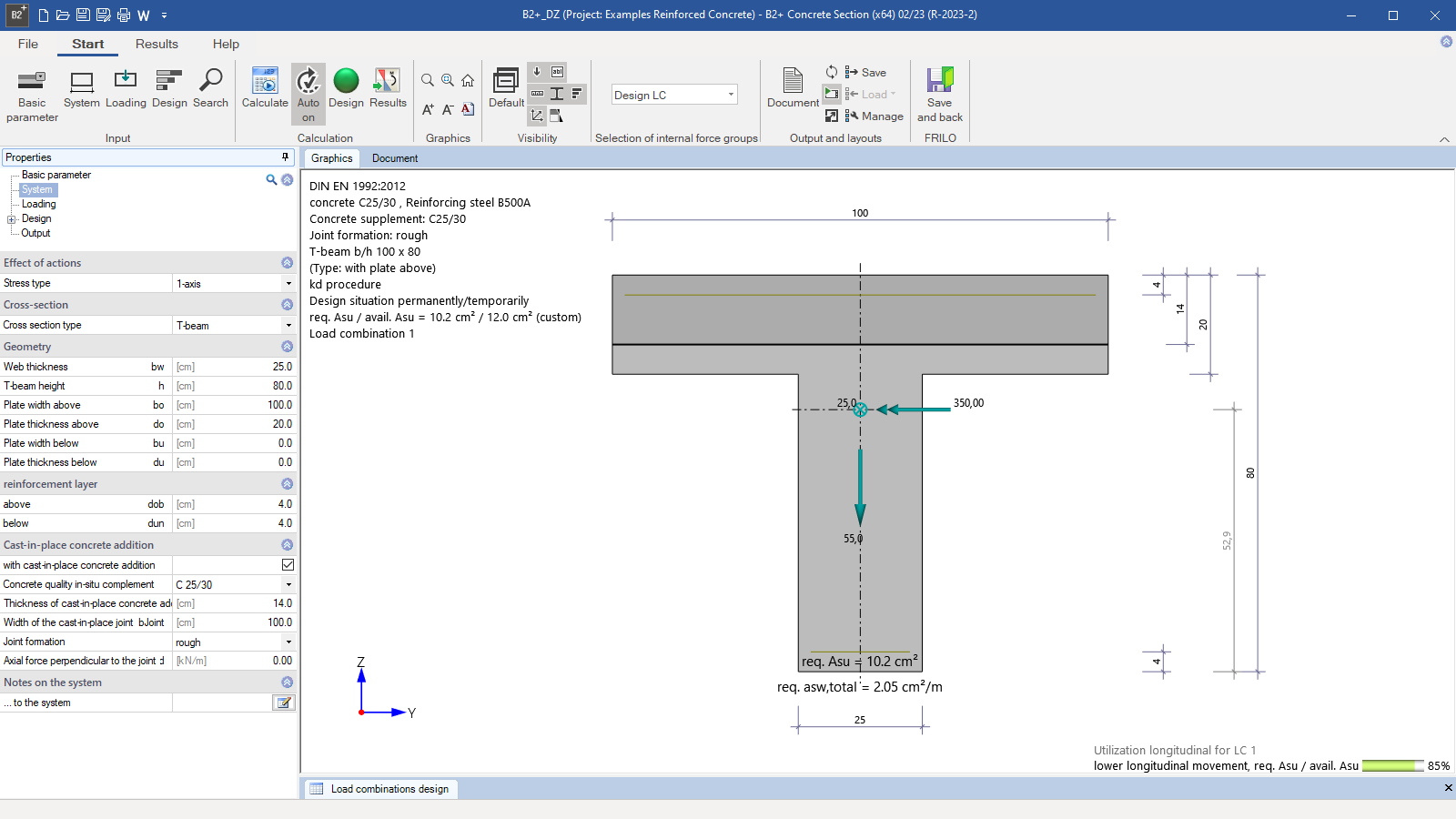
- T-beam, uniaxial
- Hollow box, biaxial
- Circular and annular cross-section, biaxial
- Layered cross-section, uniaxial
- Temperature analysis for rectangular and circular cross-sections with point reinforcement
- Polygonal cross-sections (currently only in old B2)
Environmental conditions
- Detailed entry of the exposure classes and the resulting durability requirements (minimum concrete class, concrete cover and requirement class for the crack-width verification)
Cast-in-place complement
- Cast-in-place concrete complements can be entered for uniaxial cross-section types
- The height and the width of the cast-in-place complement as well as the joint width are freely definable
- Available joint finishing options are very smooth, smooth, rough and interlocked
- Optionally, an axial force perpendicular to the joint can be defined
- Choice of shear reinforcement (stirrups or lattice girders with diagonals or posts and diagonals)
Load-bearing capacity
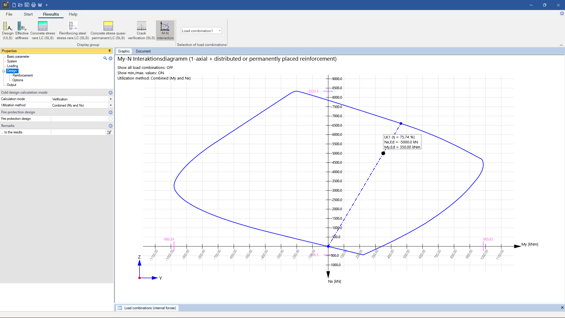
In the reinforced concrete design, the strain state leading to failure is determined for given internal forces with unknown reinforcement. For the bending design, the method with a given reinforcement ratio can be selected, and for uniaxial loading, the kd‑method is available in addition. For reinforced and unreinforced cross-sections, in addition to a design, a verification of the load-bearing capacity can also be performed. Various extrapolation variants of the entered stress are available for determining the cross-section utilization. M-N interaction diagrams can also be created for both uniaxial and biaxial bending stress.
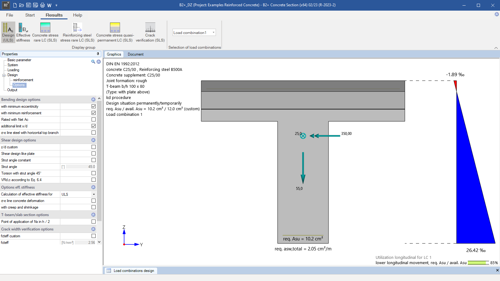
Various design options are available. Optionally, effective stiffness can be determined. The state of strain in which the external and internal forces are in balance is sought after.
In the bending design, the user can optionally calculate the net cross-sectional area of the compression zone. The calculation can include several combinations of internal forces that are to be entered via a table.
Serviceability
A crack-width verification can be performed in accordance with EN 1992-1-1. Based on the crack formula (Eq. 7.8), the maximum limit diameter, for which the permissible crack width is observed, is determined for an external load corresponding to the decisive action combination and for a selected reinforcement.
Reinforcement
For rectangular cross-sections subjected to uniaxial bending, reinforcement with carbon concrete (CARBOrefit®) can be designed in accordance with the approval. It is possible to perform a bending and shear force design in the GZT, taking into account the pre-stretching of the components, as well as a load-bearing capacity determination for the shear joint between the reinforcement and the existing structure. This feature can currently only be used in the old B2, which is supplied with the purchase of the “Verification of Reinforced Concrete Cross-Sections” program.
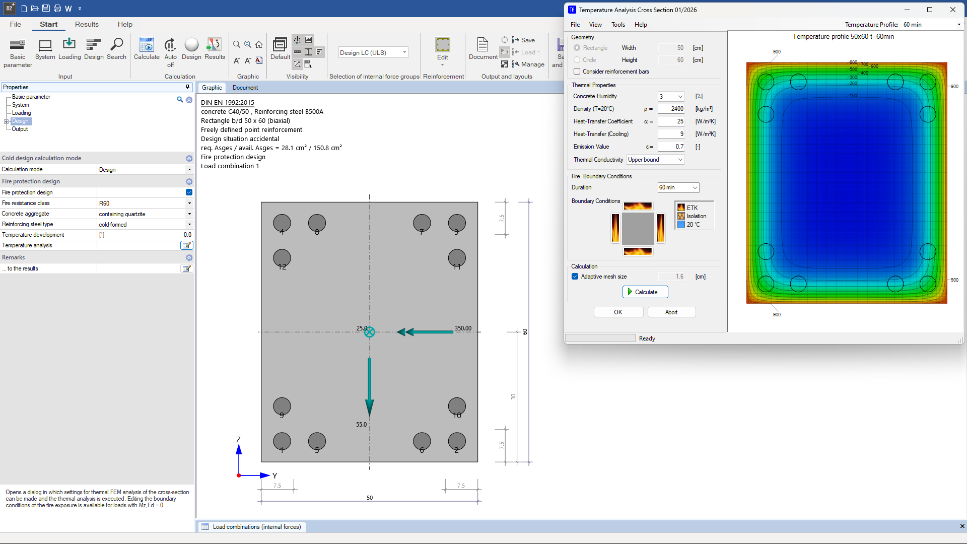
Temperature analysis
The verification in the accidental design situation fire according to EN 1992-1-2 (with National Annex) is possible for rectangular and circular cross-sections with general point reinforcement. The verification is carried out in accordance with the requirements of a general calculation method. It includes a FEM-based temperature analysis according to the parameters defined in the national annexes as well as a mechanical analysis in the form of determining the internal forces with the stress-strain curves of concrete and steel according to EN 1992-1-2 and determining the equilibrium with the external internal forces taking thermal expansion into account. Different fire resistance classes can be selected. In addition, various settings for concrete aggregate and steel production are available.
Polygonal cross-sections
For polygonal cross-sections with up to 100 straight segments, a design for biaxial bending with longitudinal force can be performed or the effective stiffness can be determined. During the design, the strain state at the ultimate limit state for cross-section failure is determined for given shear forces N, My, Mz, at which the internal shear forces of the concrete and reinforcing steel and the external shear forces are in equilibrium. The internal shear forces of the concrete are determined by dividing the concrete compression zone into thin strips. The internal shear forces of the steel include components for the reinforcement points defined with a constant area as well as for the points whose area is variable during the iteration and is only determined afterwards from the equilibrium conditions. This feature can currently only be used in the old B2, which is supplied with the purchase of the “Verification of Reinforced Concrete Cross-Sections” program.
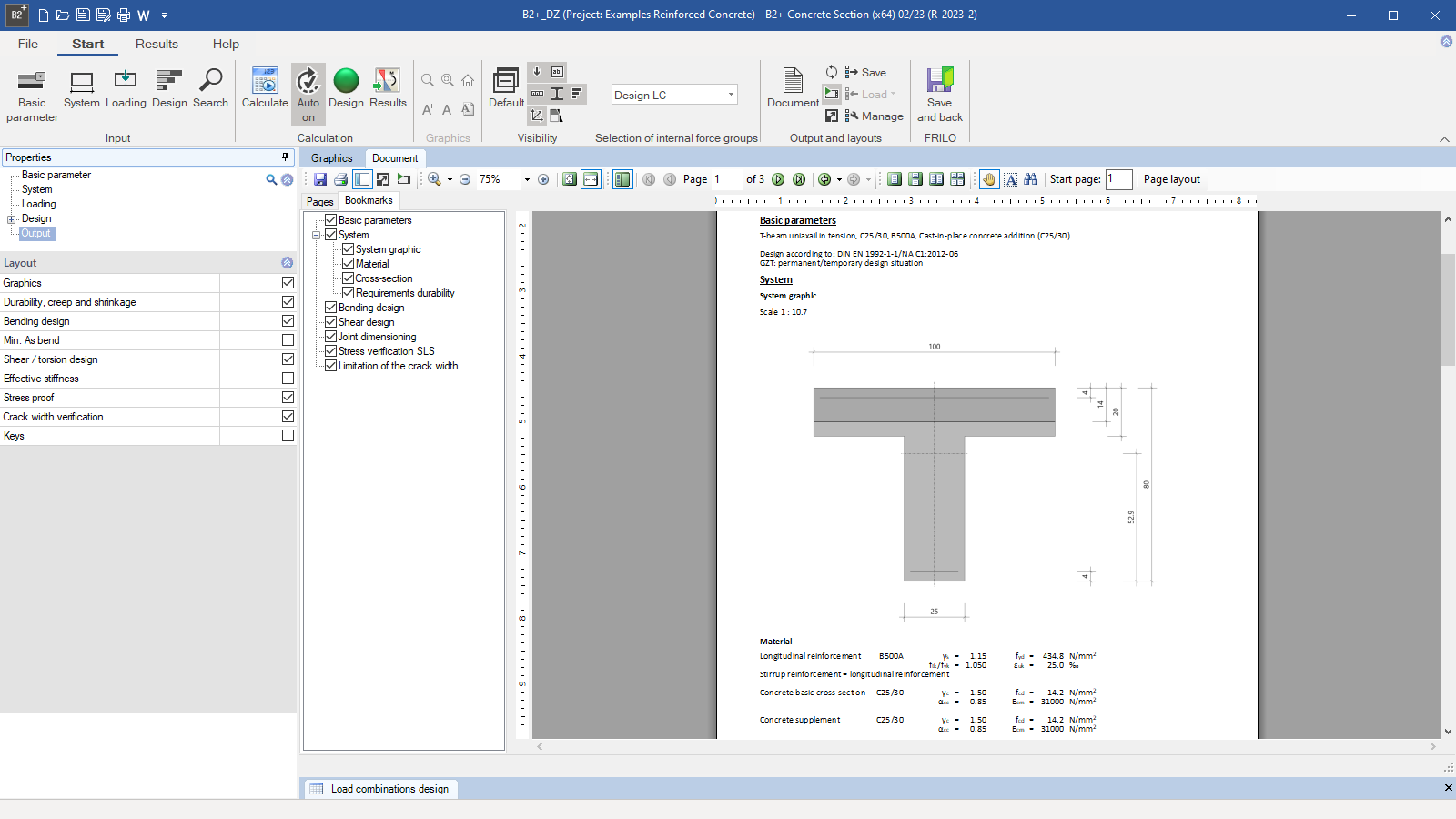
Output profile
- The user can define the desired scope of data to be put out via the options of the output profile
- The cross-section, the reinforcement and the state of strain of the selected verification can be represented in the graphical view
File formats
- Word
- Printer
Import options
- FRILO XML
Export options
- Word
- FRILO XML
Reinforced concrete
- DIN EN 1992
- ÖNORM EN 1992
- BS EN 1992
- PN EN 1992
- EN 1992
- NEN EN 1992
- NBN EN 1992
- CSN EN 1992
- NF EN 1992
Support resources
News

Corporate headquarters as reinforced concrete skeleton structure
With the construction of a new corporate headquarters, Heidelberg Materials has demonstrated the remarkable range of reinforced concrete as an attractive building material. FRILO and Allplan were used by the structural engineers.
FRILO launches version 2024-2 with powerful updates for structural analysis and design
Highlights include the optimised design of Schöck Isokörbe®, the advanced integration of DC foundation engineering programs into the FRILO environment and new RSX interfaces for detail verifications in steel construction.