
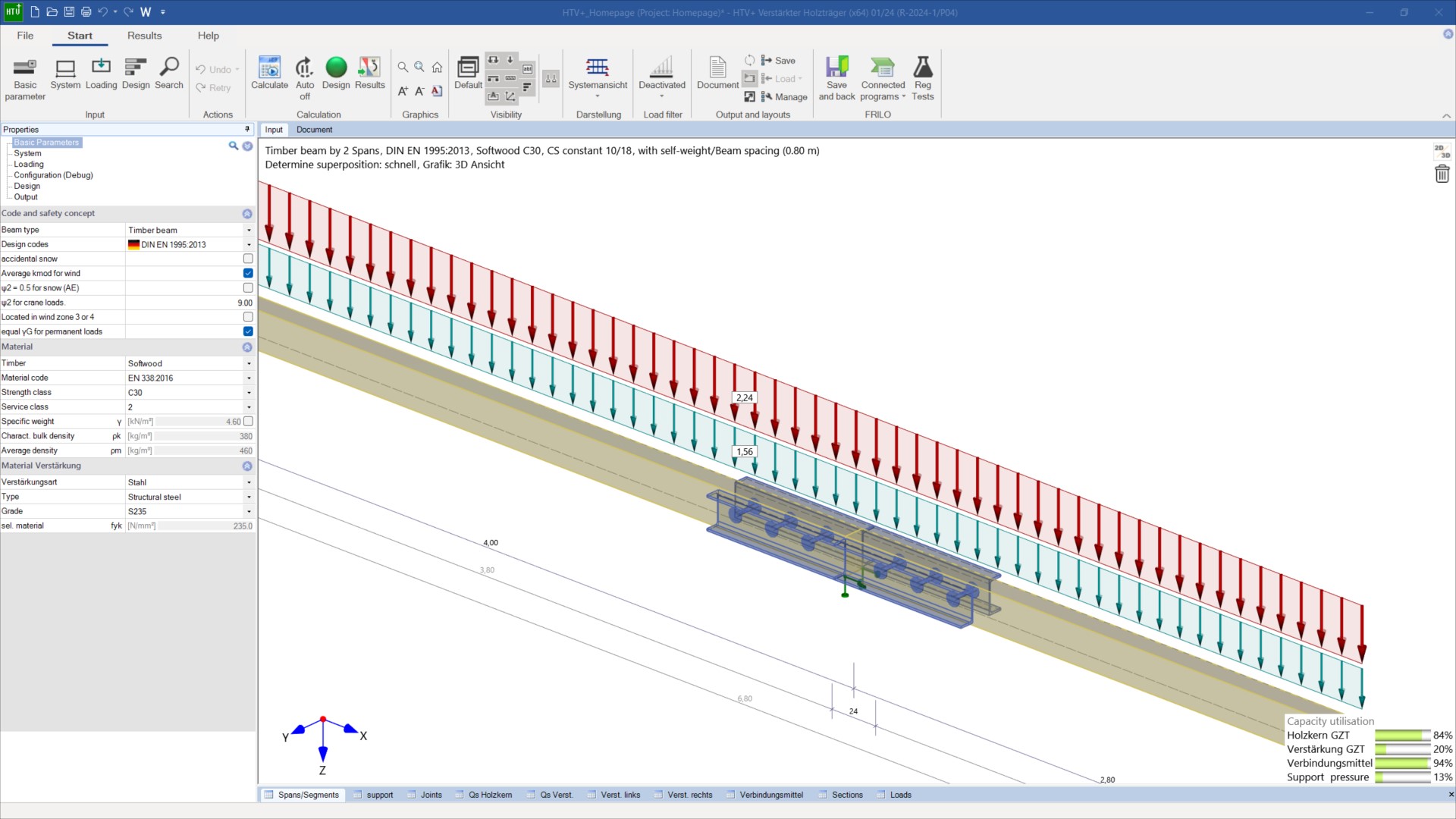
Reinforced Timber Beam
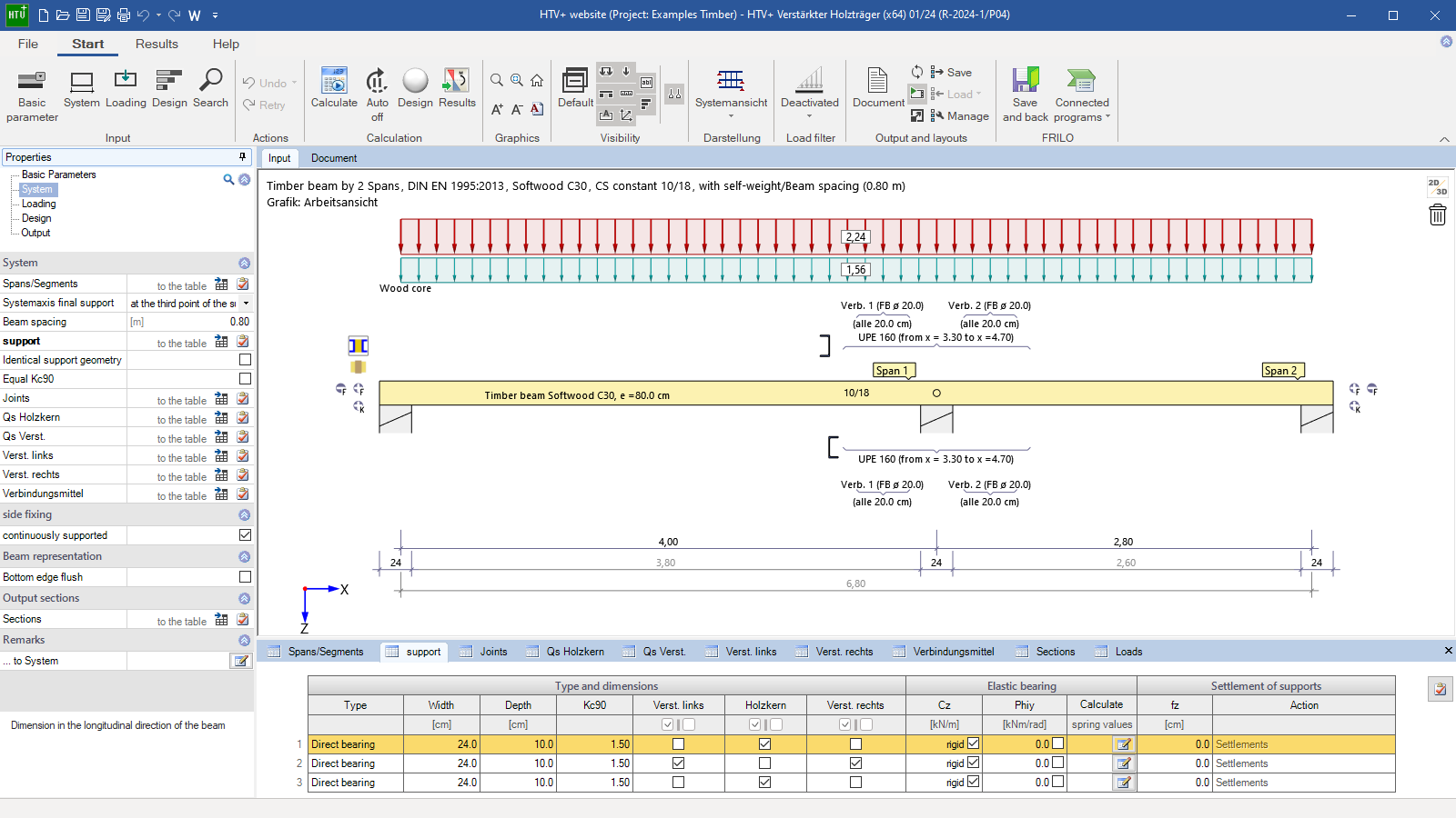
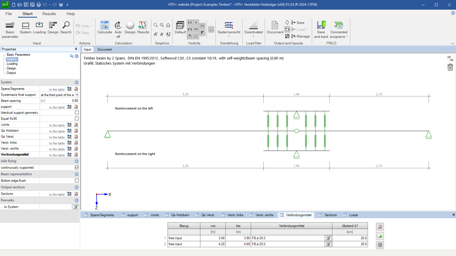
The “Reinforced Timber Beam” program analyzes single and multi-span timber beams with variably definable lateral timber or steel reinforcements. The lateral reinforcements are connected to the timber core as a coupled system using a selection of fasteners. In addition to the free choice of supports for the different static systems, the loadings can be freely applied to all members. The coupled system is calculated using a truss analysis and the loads are distributed across the fasteners. Three different views of the system are offered for optimal input.
Only available in FRILO Ultimate
Core capabilities
Material
Timber core and timber reinforcements:
- softwood of strength class C14 to C50
- hardwood of strength class D18 to D80
- glued laminated timber GL20c to GL32c or GL20h to GL32h
Steel reinforcements:
- Structural steel S235 to S450
- Structural steel annealed S275N to S460N or S275NL to S460NL
- Structural steel thermo S275M to S460M or S275ML to S460ML
- Structural steel weather resistant S235W to S355W
- Heat resistant steel S640Q, S640QL, S640QL1
- Hollow section hot S235H to S355H
- Hollow section hot N S275NH to S460NH or S275NLH to S460NLH
Structural system
- Single-span or multi-span beams with or without cantilevers
- Variable cross sections of the timber core per span and section
- Separate choice of supports for timber core and reinforcements
- Freely definable reinforcements (timber or steel reinforced)
- Adjustable lateral restraints
- core failure definable
Cross-sections
- Timber core and timber reinforcement as a rectangular cross-section with any choice of width and height
- Steel reinforcement as channel sections (UPE, UPN or UNP) or L-sections (equal-leg or unequal-leg) from a steel section library
- Storage of cross-sections in the database
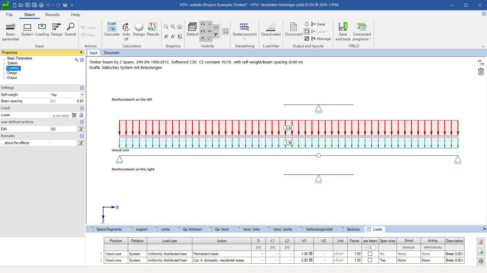
Loads
- Load types: uniformly distributed, trapezoidal, triangular, concentrated load and concentrated moment
- Free selection of the load approach on the timber core or any reinforcement
- Automatic consideration of self-weight
- Span-by-span load approach per load possible
- Consideration of a beam spacing with automatic conversion into area loads
- Definition of alternative and concurrent groups
- User-defined actions with free choice of partial safety factors
Fasteners
- Bolts, pins, threaded rods and connector joints
- Choice of distance per fastener area
- Freely definable parameters of the fasteners
- Checking the lateral fastener distances
Design basis
The calculation method used is based on a strut-and-tie model in which the timber beam is flexibly coupled to the reinforcements at discrete points via the fasteners. This allows the loads and deformations of the timber beam and reinforcement to be calculated in each section and in each fastener.
The actual support conditions and the actual load application can be considered precisely. This means that not only can the dimensions of the beams be determined, but the fasteners can be used precisely in the places where the effects of actions require it.
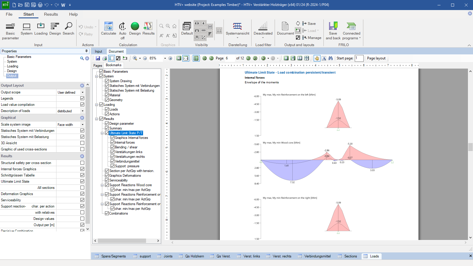
Based on the resulting internal forces, all timber cross-sections and fasteners are verified according to Eurocode 5 as well as the steel sections according to Eurocode 3.
Output profile
- short
- detailed
- custom
- ULS and SLS results, graphics, screenshots can be inserted from the “Results” area
File formats
- Word
- Printer
Data transfer options
- Direct transfer of the entire system from the DLT+/HTM+ to HTV+
- Single-span Steel Column STS+ (Support reactions)
- Timber Column HO1+ (Support reactions)
- Reinforced Concrete Column B5+ (Support reactions)
- TB-Timber Compression, Steel Plate TB-HHS (Support reactions)
- Continuous Beam Steel STM+ (entire system)
- Continuous Beam Reinforced BTM+ (entire system)
- Framework RSX (entire system)
Import options
- FRILO XML
- ASCII-file
Export options
- Word
- FRILO XML
Timber construction
- DIN EN 1995
- ÖNORM EN 1995
- NTC EN 1995
- BS EN 1995
- PN EN 1995
- EN 1995
Support resources
News

Corporate headquarters as reinforced concrete skeleton structure
With the construction of a new corporate headquarters, Heidelberg Materials has demonstrated the remarkable range of reinforced concrete as an attractive building material. FRILO and Allplan were used by the structural engineers.
FRILO launches version 2024-2 with powerful updates for structural analysis and design
Highlights include the optimised design of Schöck Isokörbe®, the advanced integration of DC foundation engineering programs into the FRILO environment and new RSX interfaces for detail verifications in steel construction.