
Timber Truss Joint
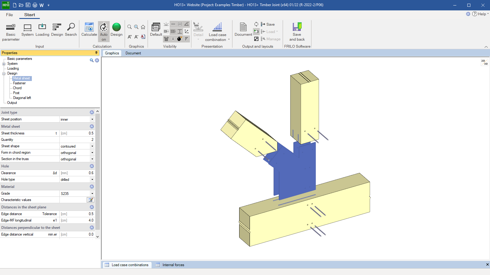
The “Timber Truss Joint” program analyzes common truss nodes in timber construction. The analysis and design of tensile splices is possible. In such a node, up to five outgoing members are connected to a central point. If the members are all of one piece, they are connected using steel plates that are either mounted to the surface or driven into slots to establish a steel-to-timber connection. Alternatively, a multi-part diagonal strut or multi-part chord can be connected in a timber-to-timber connection.
Only available in FRILO Ultimate
Core capabilities
Material
- Softwood of the strength classes C14 to C50
- Hardwood of the strength classes D18 to D80
- Glulam of the strength classes GL20c/h to GL32c/h
- User-defined material
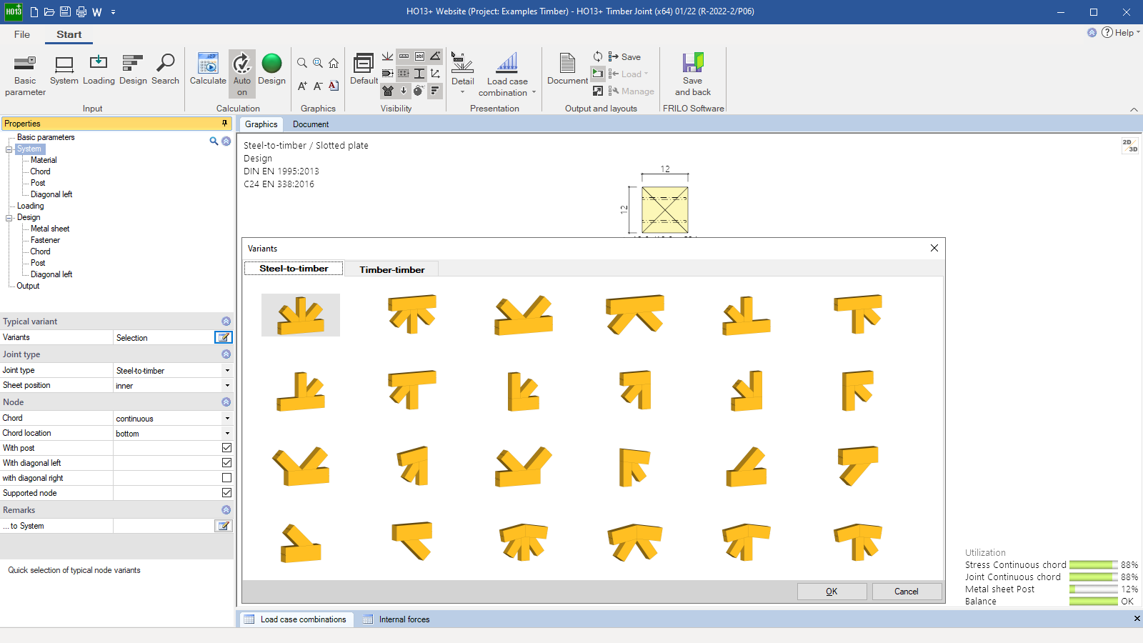
Structural system
- Timber-to-timber connection
- Steel-to-timber connection
- Chord: continuous/with pinned joint/ending on the left/ending on the right
- Position of the chord: on top/on bottom
- Post: with/without
- Diagonal strut: with/without, on the left/on the right
- Supported node
Loads
- Posts: axial forces
- Diagonal struts: axial force and shear force
- Chord timber-to-timber: moment load in the chord from external loading and eccentricity of the fasteners
Fasteners
- Dowel pins
- Fit bolts/bolts
- Nails (smooth/profiled)
- Special dowels
Verifications
The load-bearing capacity of the fasteners is verified following Johansen’s theory (accurate verification method as per EN 1995, 8.3). Suspension effects can be taken into account, if applicable.
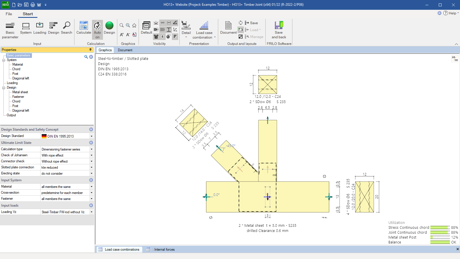
The design of the plate connection is based on the geometry of the section of the member connection and the permissible edge distances of the fasteners. The result provides an area over which the fasteners can be distributed in rows. The crack lines in the grain direction run in parallel to the edge of the component and are arranged symmetrically to the member axis. The crack lines transverse to the direction of force can optionally run perpendicular to the component edge or in parallel to the section at the member connection.
The permissible area for the arrangement of the fasteners in a timber-to-timber connection results from the intersection of the connected members and the minimum edge distances of the fasteners. The crack lines in the direction of force run in parallel to the load-introducing component and are symmetrical to the member axis of the latter. The crack lines that are transverse to the direction of force run in parallel to the edge of the load-transferring component.
For the number of fasteners, at least two fasteners are assumed in the connection area. In the area of the continuous chord, at least four fasteners are arranged. Alternatively, a fastener alone can be provided in the connection area using the basic setting “Verification”. At least four shear areas must be effective in this case. For nails and screws, a minimum quantity of two applies as a rule.
Based on the load-bearing capacity, the program determines the required number of fasteners, checks the minimum spacing to be complied with and performs the necessary verifications on the adjoining components in the area of the joint.
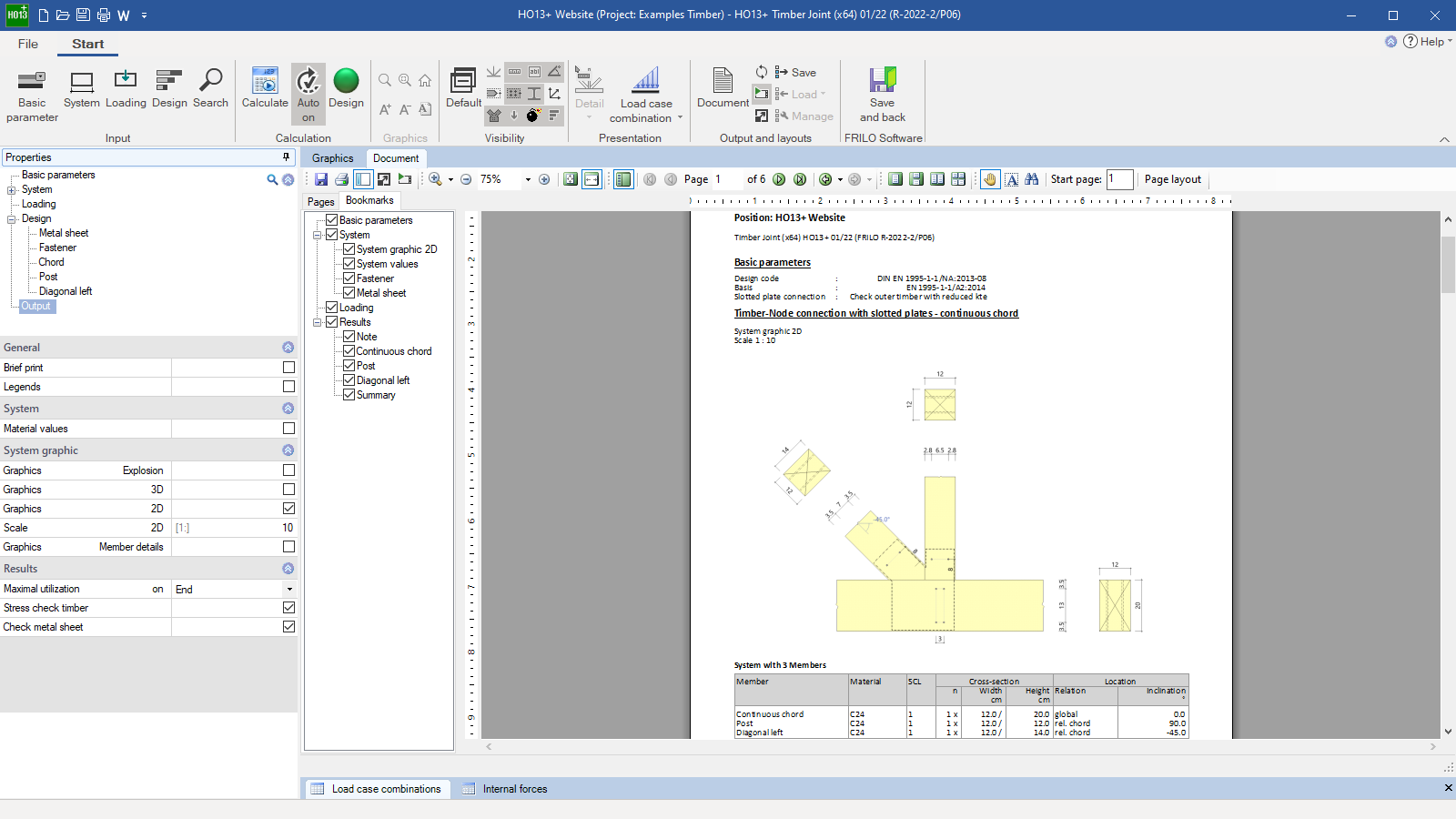
Output profile
- User-defined scope
File formats
- Word
- Printer
Timber construction
- DIN EN 1995 as well as DIN 1052
- ÖNORM EN 1995
- NTC EN 1995
- BS EN 1995
- PN EN 1995
Support resources
News

Corporate headquarters as reinforced concrete skeleton structure
With the construction of a new corporate headquarters, Heidelberg Materials has demonstrated the remarkable range of reinforced concrete as an attractive building material. FRILO and Allplan were used by the structural engineers.
FRILO launches version 2024-2 with powerful updates for structural analysis and design
Highlights include the optimised design of Schöck Isokörbe®, the advanced integration of DC foundation engineering programs into the FRILO environment and new RSX interfaces for detail verifications in steel construction.