


-
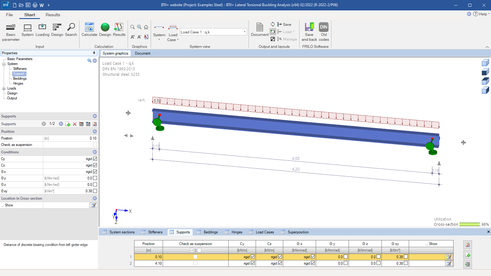
 BTII+ user interface
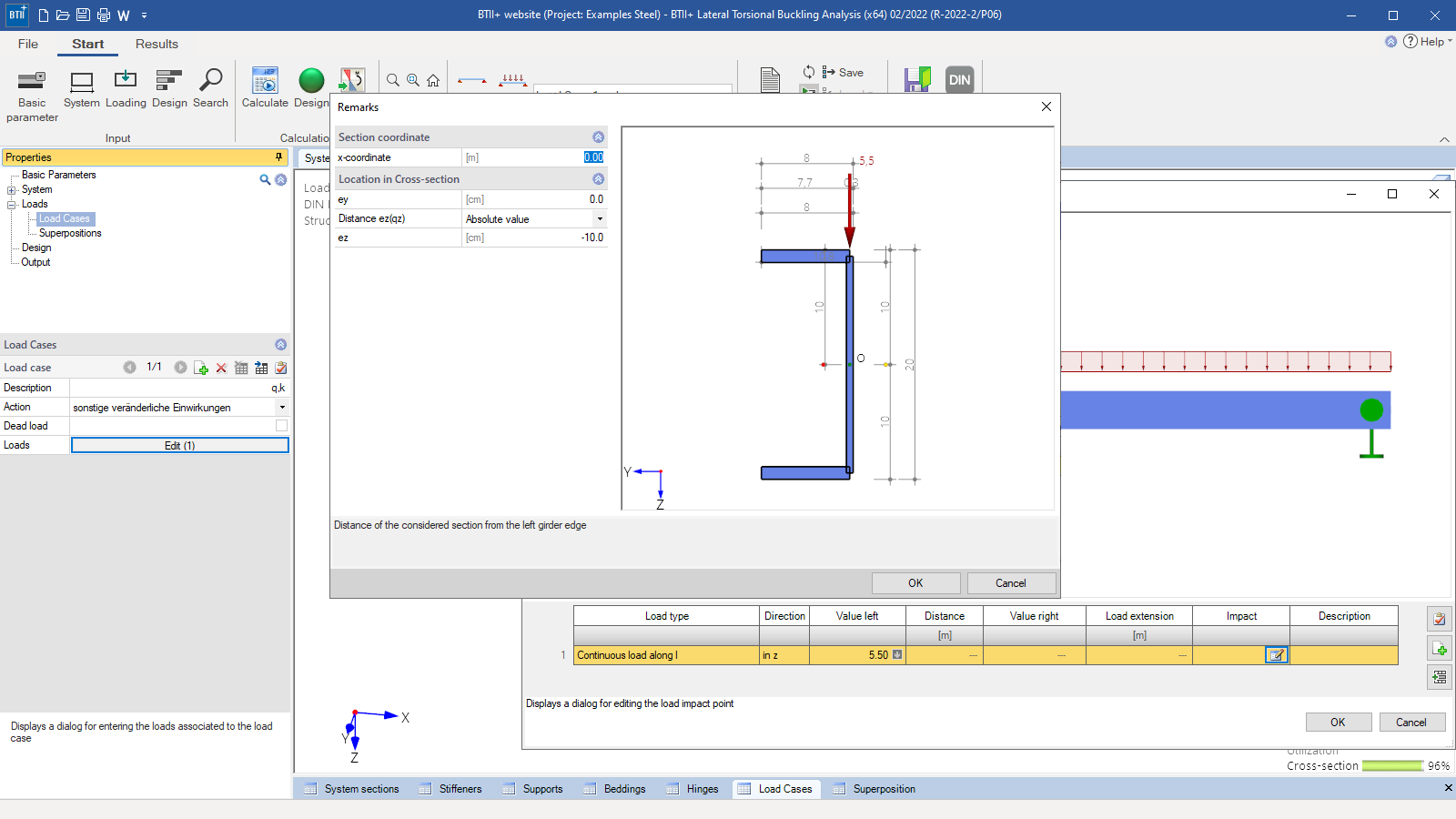
 - Entry of the loads/load application points
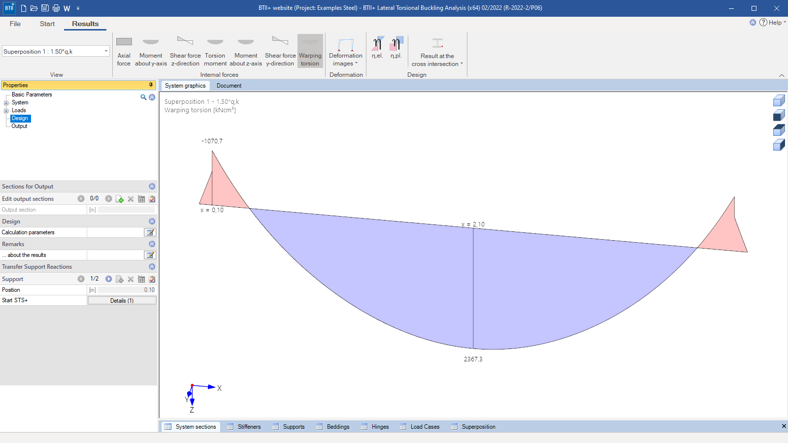
- Internal forces diagrams in the results view
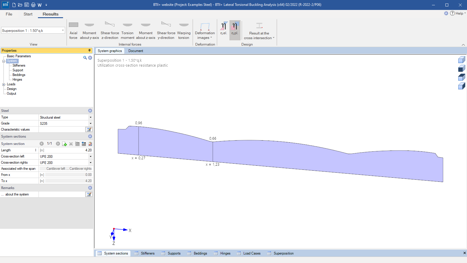
- Cross-section utilization in the results view
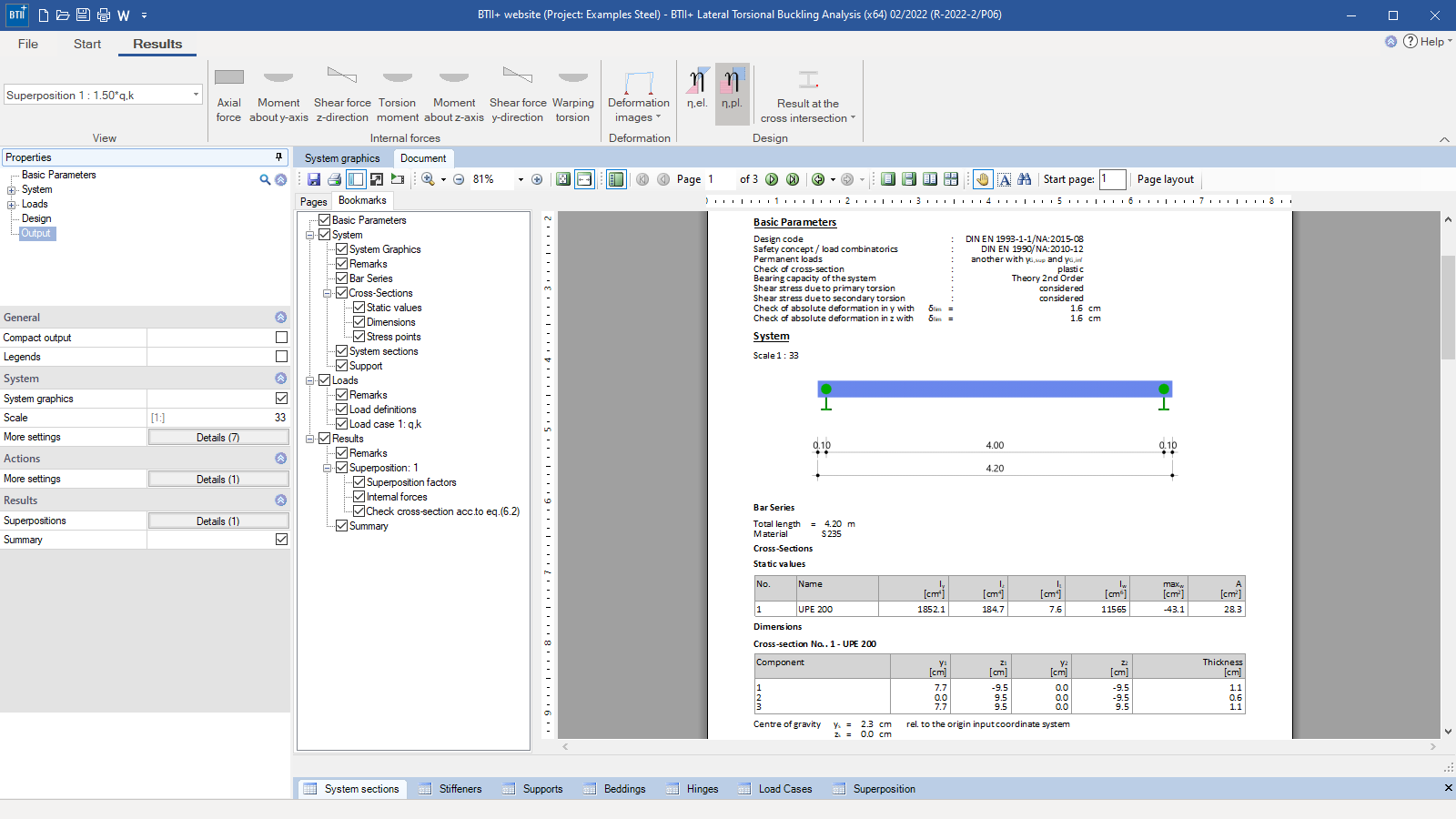
- Output document
Lateral Torsional Buckling Analysis
BTII+
BTII+ performs all structural safety analyses on straight steel member systems with any type of support. The stability verification can either be performed in a second-order buckling torsion analysis or based on the equivalent member method using ideal buckling loads. The ideal buckling loads are determined numerically on the entire system. They are calculated separately for each of the failure modes lateral buckling and lateral torsional buckling.
Discover now more programs from the section Steel!
SHOW MOREMaterial
- Structural steel: S235, S275, S355, S450
- Annealed steel (S275N – S460N)
- Thermo-steel (S275M – S460M)
- Weathering steel (S235W – S355W)
- High-temperature steel (S460Q – S460QL1)
- Hollow section, hot-finished (S235H – S355H)
- Hollow section, hot-finished, fine-grain (S275NH – S460NH)
- User-defined steel
- Aluminium (extruded, drawn, sheeting, forged products and user-defined type)
Structural system
Available systems:
- Straight member systems with any kind of support
- Modelling of components with haunches and/or cross-section discontinuities
Cross-sections:
- Double-symmetrical rolled I-sections and symmetrical and double-symmetrical user-defined I-cross-sections (rolled or welded) with and without top flange angles
- U-sections (standard and user-defined)
- Circular, square and rectangular hollow sections (standard and user-defined)
- Round and flat steel (standard and user-defined)
- Any symmetrical or asymmetrical, open, thin-walled cross-sections (defined in BTII+ or imported from Q3)
Supports:
- Any type of support possible (horizontal, vertical, torsion and warping, each definable as rigid support or springs)
- Supports can be defined at different x-coordinates
Foundations:
- BTII+ allows the mapping of elastic translational foundations, shear field foundations and torsional foundations
Joints:
- BTII+ allows the definition of shear force joints, moment joints and warping joints at any point in the structural system
Loads
- The loads are entered load case by load case.
- Load case superpositions must be defined by the user.
- When a second-order analysis is performed, initial imperfections can be taken into account for each load case combination.
- Self-weight can be considered automatically.
- Vertical and horizontal loads are mapped as concentrated, triangular or trapezoidal loads with freely definable load application points.
- Axial forces are represented by distribution diagrams.
- Moments can be defined as individual moments (about the y- or x-axis as well as warping moment) or as torsional region moment.
- Pre-deformations:
To take pre-deformation into account either in the form of initial bow imperfections in the direction of both major axes of the cross-section or the form of initial sway imperfections around the longitudinal axis, the user simply must specify the zero-points and the amplitudes of the sinusoidal or parabolic half-waves. - Moving loads:
Point loads can also be classified as a load train. In this case, limit load positions can be defined. The criterion for the decisive load position is the maximum/minimum values either of the internal forces or the axial stress or the equivalent stress. The program performs automatically the structural safety analysis according to the selected format for the decisive load position.
Analysis of the system's bearing capacity
First-order analysis:
Internal forces, deformations and stresses are calculated in first-order analyses. The load-bearing capacity of the system (stability verification) is not verified in this type of analysis!
Second-order analysis:
The calculation is performed in a second-order bending torsion analysis. The internal forces, deformations and stresses are determined with consideration of warping torsion in second-order analyses. The verification of the cross-section is performed at the stress level with γM,1, which means that no further stability verifications are necessary.
Equivalent member method:
When using the equivalent member method for the examination of the lateral buckling and lateral torsional buckling behaviour, BTII+ performs an eigenvalue calculation by applying the linear subspace method. The resulting ideal buckling loads Nki,y, Nki,z and Mkiy are used to calculate the corresponding effective slenderness ratios. These ratios allow the calculation of the relevant reduction factors for the bearing resistances, which are required for the stability analysis. In addition, the verification of the cross-sectional resistance is performed.
Analysis of the cross-sectional resistance
The criteria and methods applying to structural safety verifications of cross-sections are stipulated in EN 1993-1-1 section 6. The related verification equations take the classification of the cross-sections into account and refer to the elastic or plastic cross-sectional properties that are determined by the class of the cross-section. When selecting the “plastic” verification method, the resistance to the internal limit forces is verified.
Elastic – Cross-section verification as per EN 1993-1-1, equation 6.1:
The design values of the internal forces calculated in accordance with the theory of elasticity are used to determine the axial and shear stresses acting on the cross-section based on the principles of the mechanics of materials. These stresses are compared to the design value of the yield strength. The structural safety of the cross-section is ensured when the loading in all cross-sectional parts is smaller or at most equal to the design values of the resistances. The plastic bearing reserves are not taken into account.
Plastic – Cross-section verification as per EN 1993-1-1, equation 6.2:
The internal forces and deformations are calculated based on the theory of elasticity. The design values of the resistances result from the utilization of the plastic load-bearing capacity. The structural safety of the cross-section is ensured when the design values of the internal forces do not exceed the limit internal forces in the plastic state.
Serviceability verification
In connection with the verification of the serviceability, the program determines the deformations of the structural system. The user must specify the load-case combination(s) as well as the design situation(s) and deformation limits for the verification of the serviceability.
Document file formats
- Word
- Printer
Output
Output profiles:
- Pre-set brief output or user-defined scope
Result graphs:
- Internal forces: N, My, Qz, MT, Mz, Qy, Mw
- Deformations, torsion, warping
- Stresses: σ,x ; τ ; σ,v
- Utilization Eta: n,el ; n,fat
- Results at the individual cross-section points (axial stress, shear stress and equivalent stress)
Transfer options
- Single-span Steel Column STS+
- Timber Column HO1+
- Reinforced Concrete Column B5+
Import options
- ASCII-file
- ASCII-file (with selectable options)
Export options
- Word
- ASCII-file
Steel construction
- EN 1993
- DIN EN 1993
- ÖNORM EN 1993
- BS EN 1993
- DIN EN 1999

News

Efficient design of load-bearing steel structures in second-order torsional buckling analyses
The calculation program Lateral Torsional Buckling Analysis BTII+ from the software manufacturer FRILO provides for enhanced stability verifications of steel structures in second-order torsional buckling analyses.
FRILO launches version 2024-2 with powerful updates for structural analysis and design
Highlights include the optimised design of Schöck Isokörbe®, the advanced integration of DC foundation engineering programs into the FRILO environment and new RSX interfaces for detail verifications in steel construction.
Events
You may also be interested in these programs

