


-
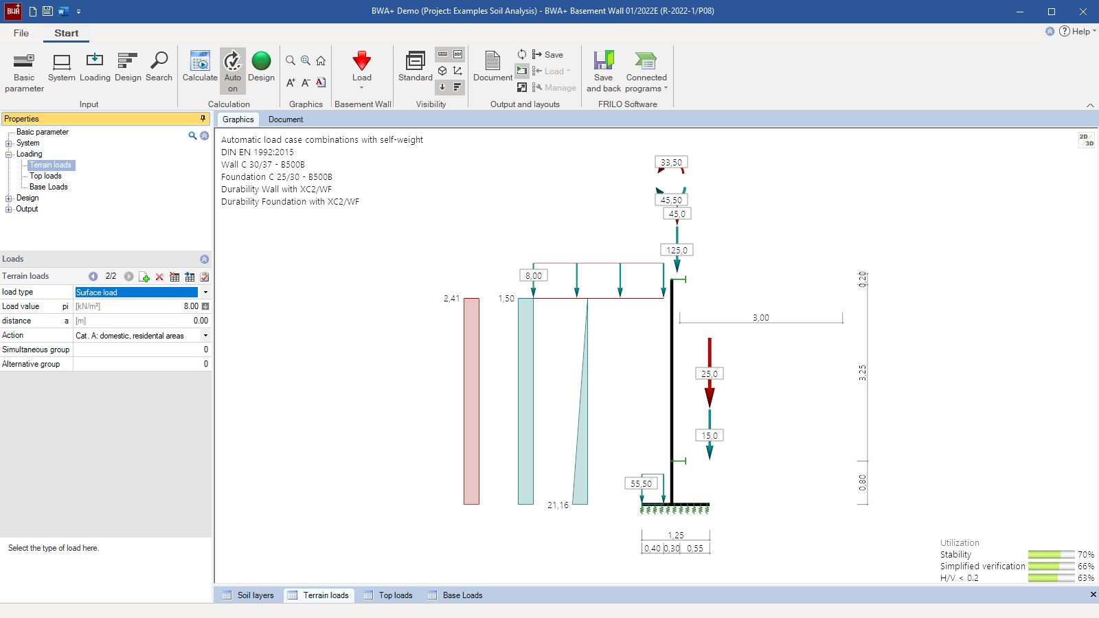
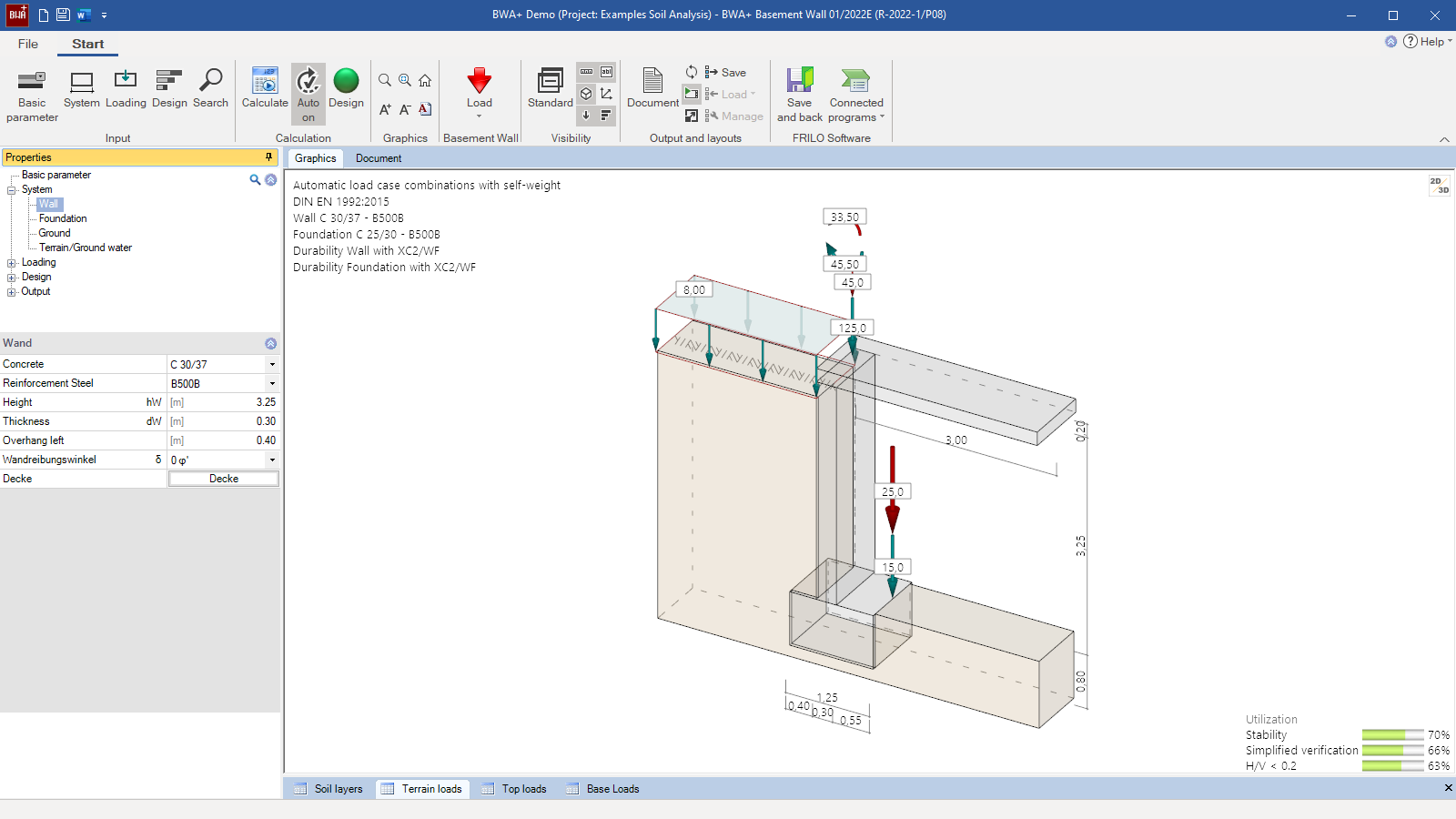
 Structural system and actions
 - BWA+ user interface
- System consisting of the slab above, the wall and the foundation
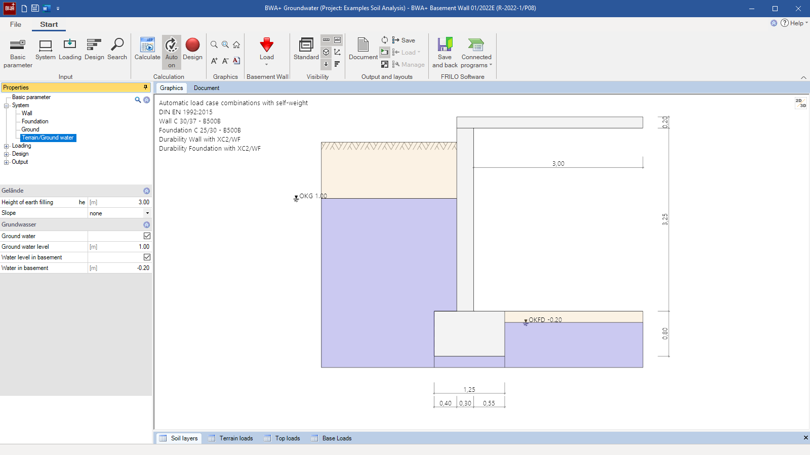
- Different groundwater levels on either side of the wall
Basement Wall
BWA+
The BWA+ program is used to design basement walls of reinforced concrete, which can be loaded by vertical loads and moments at the top and by earth pressure on one side. For the foundation, the simplified base pressure verification as per DIN 1054 as well as the bending and shear design are performed. The basement wall is considered as a vertical member with a pinned or restrained top and a base restrained between two continuously supported members simulating the foundation.
Discover now more programs from the section Foundation Engineering!
SHOW MOREMaterial
- Reinforced concrete with selectable wall friction angles
- Material quality separately selectable for the foundation, the wall, and the floor
Structural system
- Freely selectable geometry and position of the wall
- Type of support (pinned, partly of fully restrained) and stiffness between wall and floor slab on top
- Geometry and continuous support of the foundation
Soil:
- Freely selectable soil parameters
- Any number of soil layers
- Base pressure resistance according to empirical values from DIN 1054 or specified by the user
Ground surface:
- Horizontal, continuously ascending, or broken slope
- Height of the earthfill for the calculation of the earth pressure
Groundwater:
Optionally, different groundwater levels can be defined on the basement side and on the earth pressure side. The actions caused by the differential water pressure and by buoyancy are automatically derived from these specifications.
Loads
- Any ground-surface loads in the form of area loads, strip loads, block loads, and line loads.
- Vertical concentrated loads and concentrated moments applying to the wall head as well as concentrated loads applying to the foundation edge.
- Free assignment of loads to types of actions according to EC 0 as well as to concurrency and alternative groups.
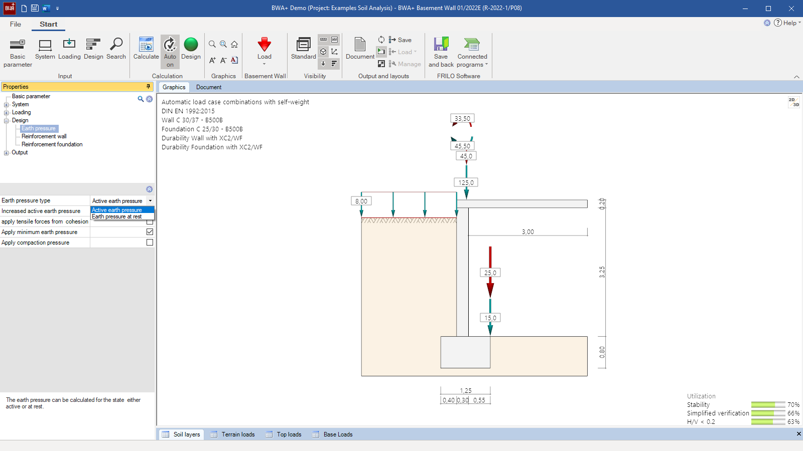
Earth pressure
- Earth pressure at rest, active or any increased active earth pressure
- Optionally with minimum or compaction earth pressure
- Compaction earth pressure and minimum earth pressure optionally available
Reinforced concrete design of the wall and the foundation
- Specification of the concrete cover, the reinforcement layer and the minimum diameter
- Durability verification via exposure classes
- Consideration of a minimum reinforcement quantity
- Optionally, different design options for the wall and the foundation
- Shear verification as a plate and design in the contact face optionally available
Geotechnical verifications
- Simplified verification with base pressure resistances (either user-defined or taken from tables of DIN 1054)
Document file formats
- Word
- Printer
Output
- Overview of the decisive load case combinations
- Tabular output of the selected earth pressure and water pressure distributions
- Geotechnical verifications in the ULS, simplified with base pressure resistance
- Decisive base pressure distribution for the design of the toe or heel and the foundation
- Tabular Internal forces behaviour inside the wall
- Verification of the resistance to bending and shear force in the ULS with output of the required reinforcement for the wall and the foundation
- Stability verification of the wall
Transfer options
- Framework RSX
Geotechnical standards
- DIN EN 1997
- DIN 1054
- ÖNORM EN 1997
Reinforced concrete
- EN 1992
- DIN EN 1992
- ÖNORM EN 1992
- PN EN 1992
- BS EN 1992
- NTC EN 1992
- DIN 1045-1
- ÖNORM B 4700
Support resources

News

FRILO launches version 2024-2 with powerful updates for structural analysis and design
Highlights include the optimised design of Schöck Isokörbe®, the advanced integration of DC foundation engineering programs into the FRILO environment and new RSX interfaces for detail verifications in steel construction.
Load determination for eight-floor perimeter block development with FRILO Building Model
Find out how the structural engineers at bauart Konstruktions GmbH determined the loads for an eight-floor perimeter block development in Frankfurt’s Europaviertel district using the GEO from FRILO.
Events
You may also be interested in these programs

