
Load Transfer
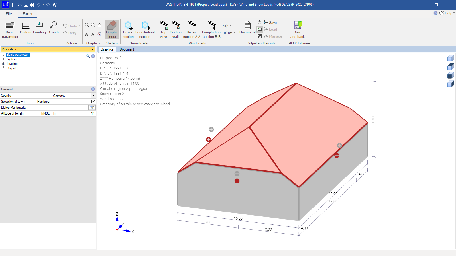
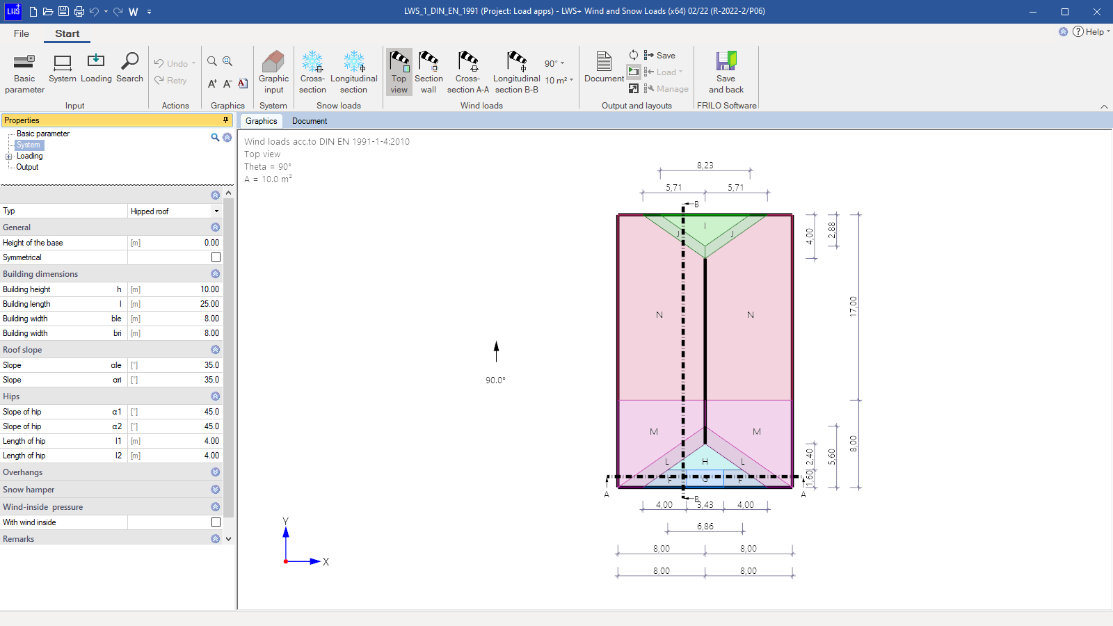
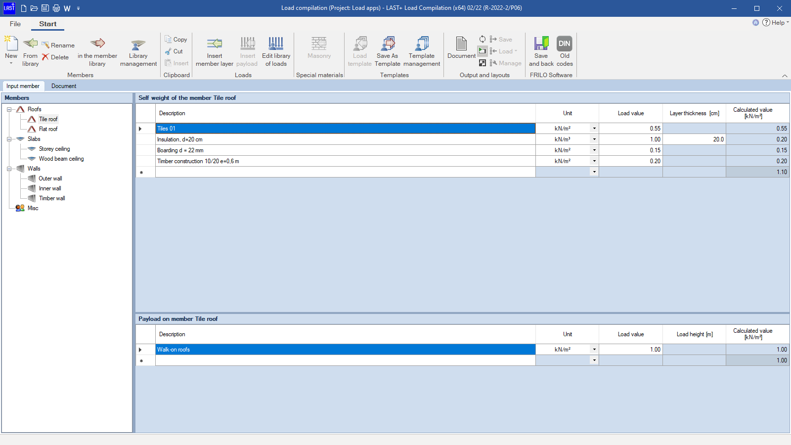
The “Load Transfer” module can be used to determine the vertical and horizontal load transfer for building constructions made of concrete and masonry. The vertical load transfer is analyzed floor by floor from top to bottom based on the stiffness of the individual floor storys. In addition, wind and snow loads for gable roofs, hipped roofs, and monopitch roofs can be analyzed. It is also possible to compile area-related dead weights and predefined live loads for roof, ceiling, and wall components.
Also available in FRILO Professional und FRILO Ultimate
Core capabilities
The program can be used to define standard concrete and masonry construction buildings with all structurally relevant components and loads. Vertical load transfer is determined story by story from top to bottom based on the stiffness of the individual story levels. A finite element analysis is performed on each story level. The support forces at the base of the load-bearing components are distributed evenly over the length of the component and transferred to the story below until no more stories are found and a foundation is automatically generated.
Data entry
Most data are entered interactively in the graphical user interface. To support this, DXF slides can be read in and self-defined auxiliary structures or auxiliary grids can be used. Thanks to a locally definable coordinate system and direction-oriented data entry, points/components can be defined easily and accurately via the graphical user interface or by entering numerical coordinates. The Undo/Redo functionality allows work steps to be undone/restored, which supports a safe and effective workflow. Various import options, for example via the FRILO BIM-Connector®, top off the data entry.
Coupling
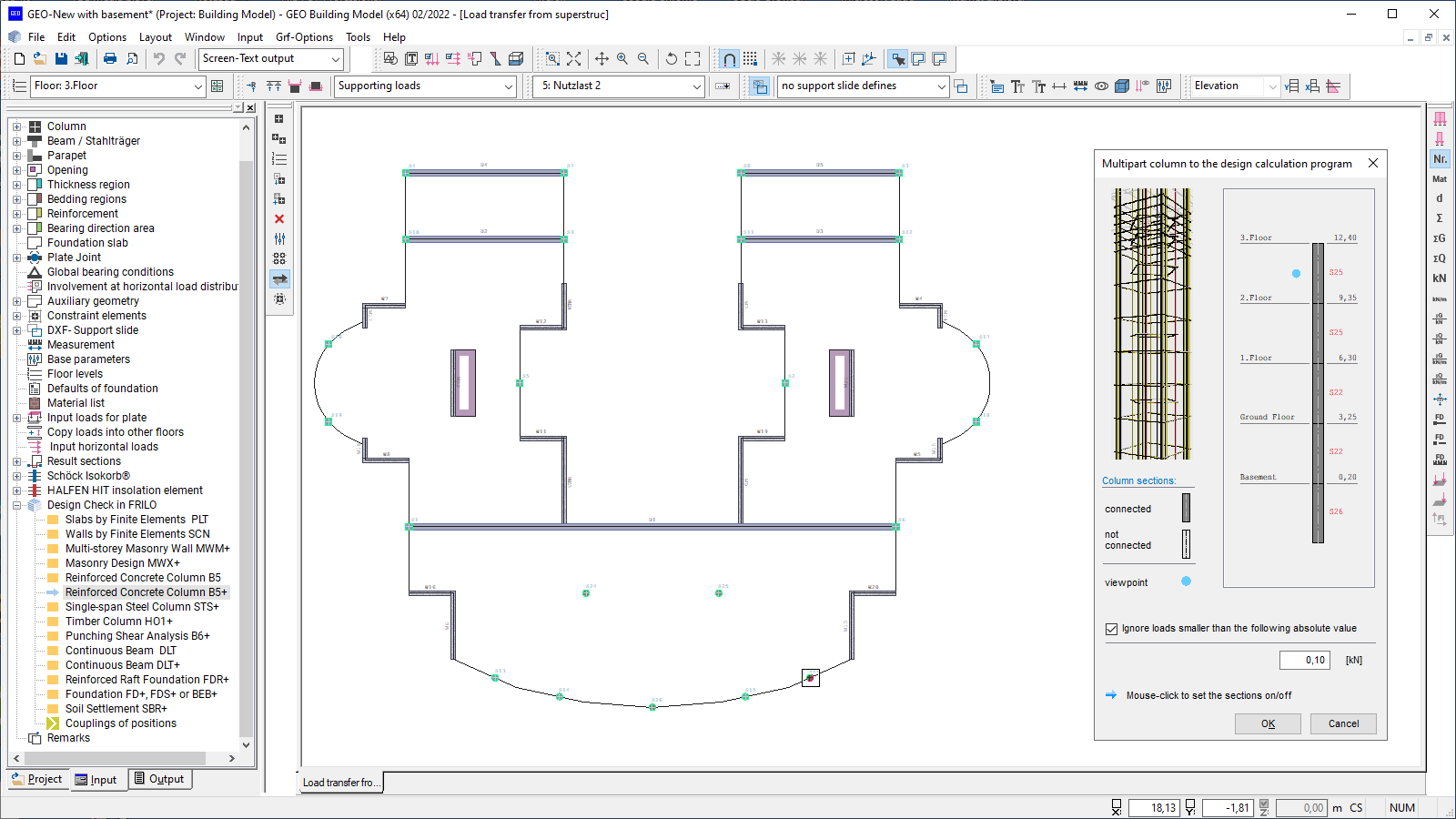
If a component is transferred from this program to another FRILO application for the design, the user can register this item in the building model as a coupled (linked) item. If the corresponding component is accessed subsequently, this item is proposed before the transfer. In most design programs, a coupled item can be used as a template to specifically adopt or adjust properties and loads.
Instability examination
In order to assess the rotational and lateral stiffness of the building, instability factors are determined. If these are complied with, a more accurate verification in a second-order analysis can be dispensed with.
Bemessung
Output profile
The output profile offers a variety of setting options to create an individual structural analysis document. The scale is freely selectable.
Results
An extensive graphical and tabular output for the creation of structural analysis documents in A4 format is provided. Moreover, all graphics can be put out in the so-called drawing format. Various user-definable title blocks can be used.
Transfer from GEO to
Automatic transfer of the components to the design programs inclusive all loads and action groups:
- Plate (transfer of floor slab & all relevant components)
- Walls by Finite Elements (transfer of reinforced concrete walls)
- Multi-story Masonry Wall (transfer of walls from masonry)
- Masonry Design (transfer of walls from masonry)
- Reinforced Concrete Column
- Steel Column (transfer of cross sections & loads)
- Timber Column (transfer of cross sections & loads)
- Punching Shear Analysis
- Continuous Beam (transfer of nodal loads from FE analysis)
- Reinforced Raft Foundation (transfer of loads at the base of the walls)
- Isolated Foundation
- Strip Foundation
- Beam on Elastic Foundation
- Soil Settlement
- Pile Foundation
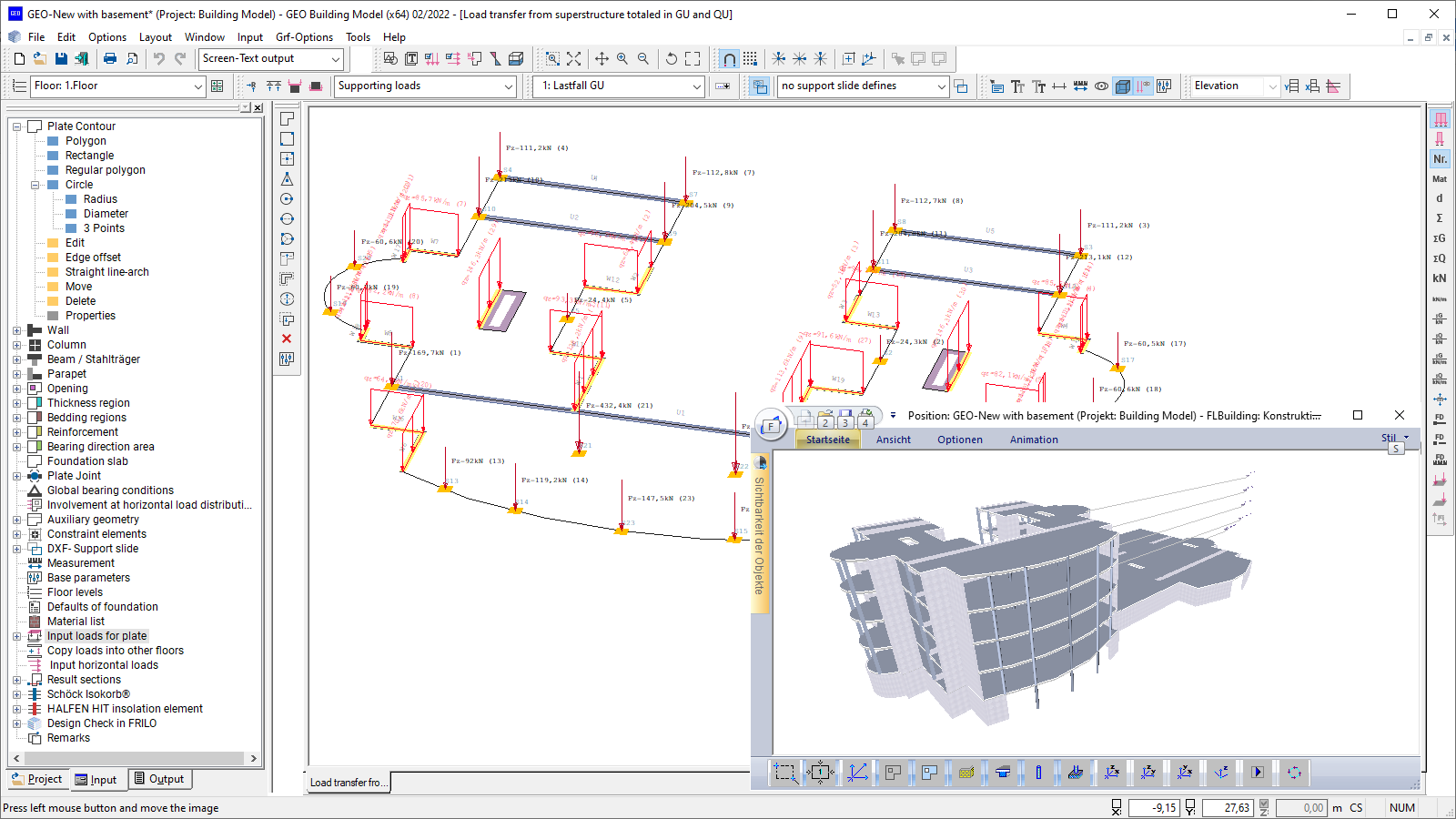
For most interfaces, the vertical support reactions can be added in two so-called superstructure load cases (GU for permanent loads and QU for live loads) or transferred as load case-specific loads in individual load cases. The action groups and alternative groups required for the superposition are also exported.
Transfer from GEO to SCIA Engineer
Transfer building models created in GEO together with the boundary conditions easily, quickly and directly to SCIA Engineer. A button for direct data transfer is integrated into the GEO program interface. When the button is pressed, SCIA Engineer is started and the building modelled in GEO is immediately displayed in 3D.
Transfer to GEO
Import options
- The basic geometric data of an entire model can be imported directly via the FRILO BIM Connector®
- Slabs defined in the “Plate” program can be imported with all loads and geometric data
- From ALLPLAN, data of the “Plate” program can be imported into the building model, if the structural components have been processed appropriately in ALLPLAN.
- Moreover, geometry data in the form of auxiliary constructions can be imported via a DXF interface from all common CAD programs. These data can be used in the program via a snap function supporting the easy entry of the geometry.
Export options
- Graphical results can be exported to a DXF file
- The user can create SAF files to transfer data to SCIA, for instance
- Load calculations, section and stress compilations as well as the quantity survey can be exported to an Excel or a CSV file
Reinforced concrete
- DIN EN 1992,
- DIN 1045/DIN 1045-1
- ÖNORM EN 1992
- ÖNORM B 4700
- UNI EN/NTC 1992
- BS EN 1992
- PN EN 1992
Masonry
- DIN EN 1996
- DIN 1053-1/-100
- ÖNORM EN 1996
- BS EN 1996
Wind loads
- DIN 1055-4
- DIN EN 1991-1-4
- ÖNORM EN 1991-1-4
- BS EN 1991-1-4
Sway imperfection
- DIN EN 1992
- ÖNORM EN 1992
- BS EN 1992
- NTC EN 1992
- PN EN 1992
- DIN 1045/DIN 1045-1
- ÖNORM B 4700
Earthquake
- DIN 4149-2015
- DIN EN 1998-1
- ÖNORM EN 1998-1
Material for steel columns
- DIN EN 1993
- DIN 18800
- ÖNORM EN 1993
- BS EN 1993
Load types
The available loads are point, line and area loads. For line and area loads, a distinction can be made between constant and non-constant loading. Moreover, temperature loads can be considered. All loads are entered in load cases. These load cases are assigned to action groups already in the building model.
Vertical load transfer
The load calculation is carried out story by story from top to bottom, whereby the loads of the upper story are passed on to the story underneath.
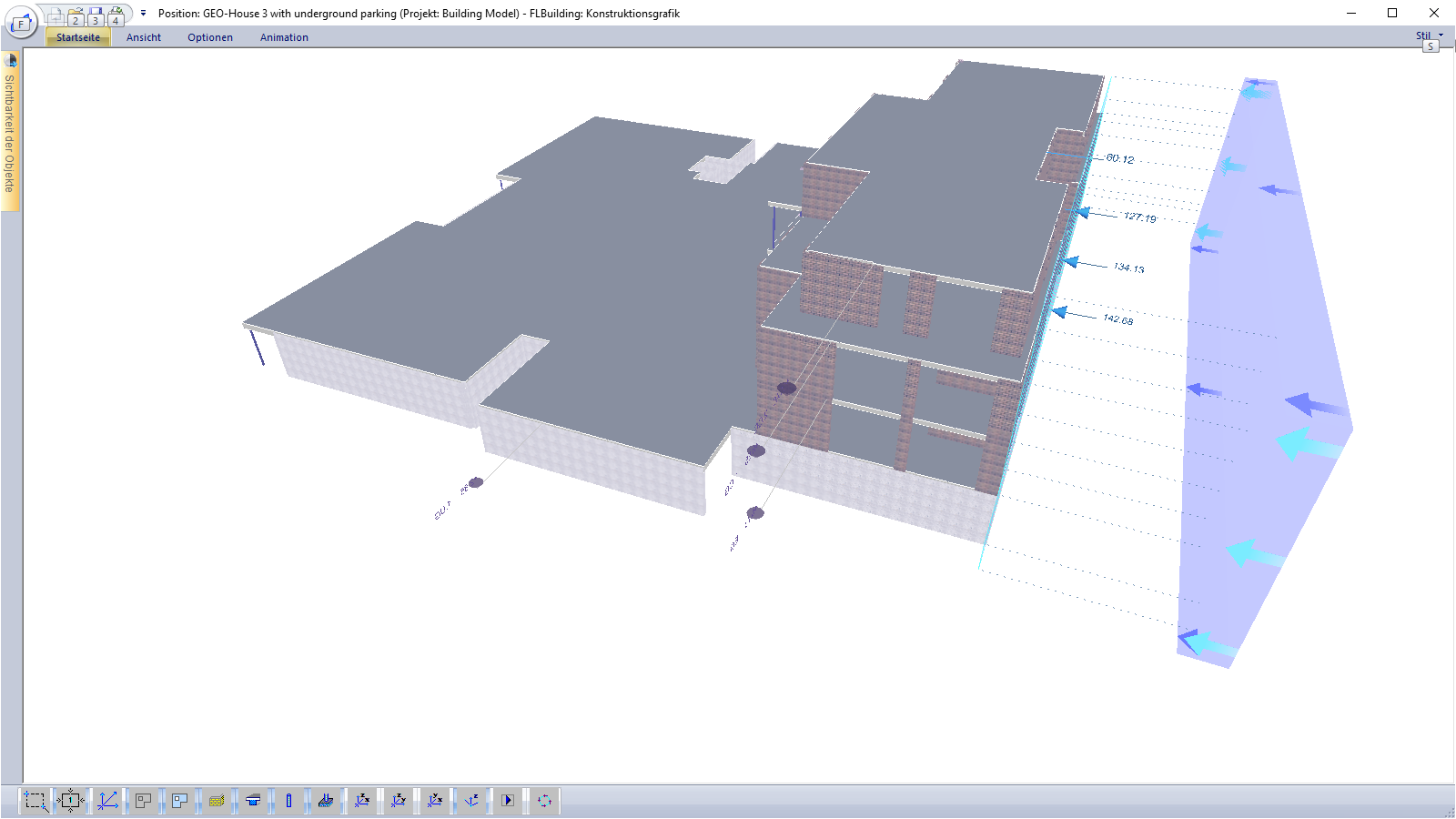
Horizontal load transfer
Horizontal loads generated by wind, inclination and earthquakes can be determined. The wind loads can be calculated depending on the building geometry and the specified wind parameters. Sway imperfections are automatically generated from the calculated vertical loads. The horizontal loads are distributed over the bracing components proportionally to the bending stiffnesses. A contribution to the horizontal load transfer can be defined for groups (e.g. only for reinforced concrete walls) or for individual components.
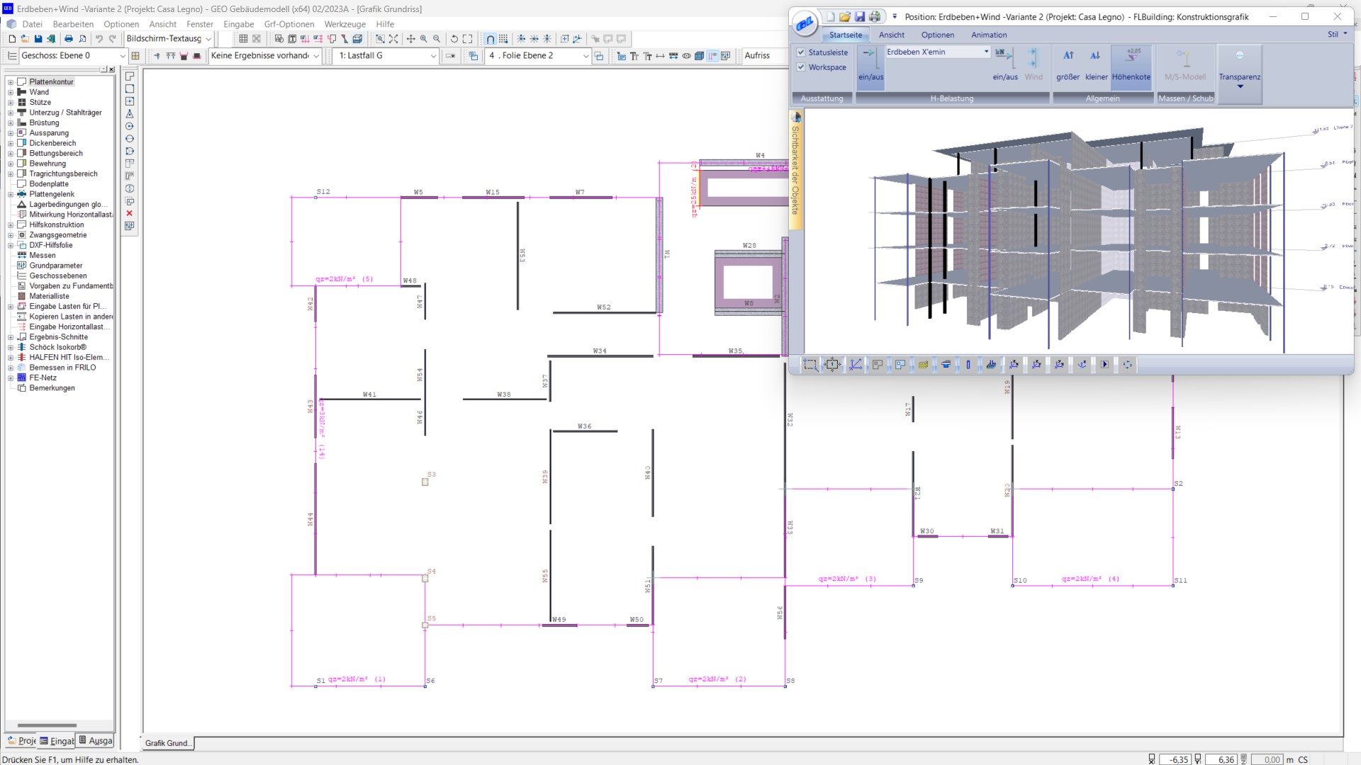
Erdbebenlasten
Seismic loads can be calculated in accordance with DIN EN 1998-1 and DIN 4149, 6.2.2 for Germany or in accordance with ÖNORM B 1998-1:2006/2011, 4.3.3.2 for Austria. The seismic loads are determined using the simplified response spectrum method. The user can either freely define the basic values for the determination of the soil acceleration response spectrum or set them automatically via the selection of a municipality. The contributing vertical loads can be taken into account from a specific selectable floor level on. Various approaches are available to determine the basic vibration duration. After the calculation, the stress behaviour and the determined seismic shares can be displayed graphically for each individual component.
Specialties
The user can subsequently copy load cases from one story to another. In addition, an automatic transfer of loads from a stored calculated GEO item is available. In the transfer process, the support reactions acting at the base of an existing item are transferred to a selected story. The user can choose whether the vertical support reactions are added up in two so-called superstructure load cases, each with a constant progression, or whether they are transferred as load-case specific loads in individual load cases. In the building model, the self-weight of all load-bearing components is automatically considered.
Slabs
All floor slabs can be defined as reinforced concrete slabs. Different thicknesses, different concrete qualities, and different load-bearing directions (uniaxial and biaxial) as well as torsionally resilient and torsionally stiff elements can be defined. The slab is supported by walls and columns or, in the case of base slabs, rests on elastic springs. By defining slab joints, bearing direction areas, reinforcement areas and subgrade areas, the user specifies additional properties that are included in a later design with the “Plate” program.
Walls
Walls are used as linear supports for the slab and can be included as rigid or elastic supports. The user can freely define the elastic support or have it automatically determined from the geometry and the material properties. Masonry and concrete are available as materials. Walls can optionally be defined individually or as a connected so-called “wall pillar”.
Columns
Columns are used as point-type supports for the slab and can be included like the walls as rigid or elastic supports. The user can freely define the elastic supports or have them automatically determined from the geometry and the material properties. Masonry, concrete, steel, and timber are available as materials.
Beams
Beams are used as linear stiffeners for the slab. Suspender and downstand beams can be defined. The user can select a concrete quality that differs from the slab concrete quality. In addition to suspender/downstand beams of reinforced concrete, also steel beams can be defined as suspender/downstand beams. All common steel shapes are available for selection.
Parapets
In contrast to suspender/downstand beams, parapets are just used to supplement the self-weight. Masonry and concrete are available as materials. Concrete parapets can also be defined as load-bearing structures. Internally, they are treated like downstand beams in this case.
Measurement of Quantities
The determination of the quantities is controlled via the output profile. The user can define the tabular output individually for the different materials and components as well as for individual storeys or even across storeys. The program does not determine the reinforcing steel quantities. The results can optionally be exported to an Excel folder or a CSV file.
Support resources
News

Corporate headquarters as reinforced concrete skeleton structure
With the construction of a new corporate headquarters, Heidelberg Materials has demonstrated the remarkable range of reinforced concrete as an attractive building material. FRILO and Allplan were used by the structural engineers.
FRILO launches version 2024-2 with powerful updates for structural analysis and design
Highlights include the optimised design of Schöck Isokörbe®, the advanced integration of DC foundation engineering programs into the FRILO environment and new RSX interfaces for detail verifications in steel construction.