
-
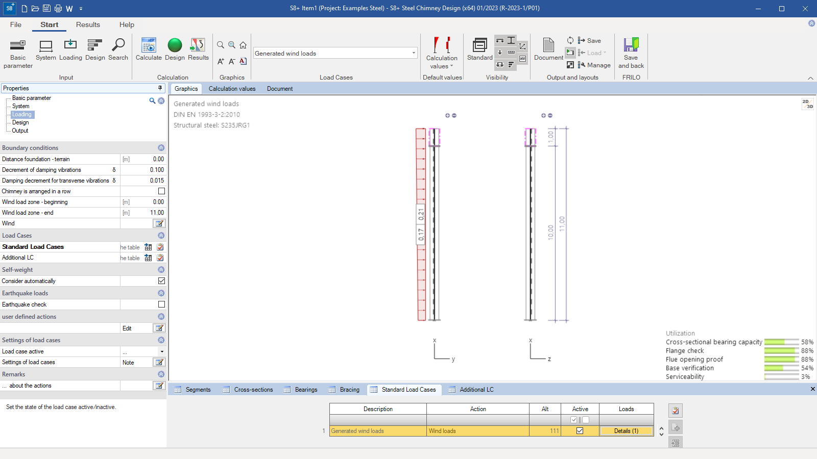 Program interface S8+
 -
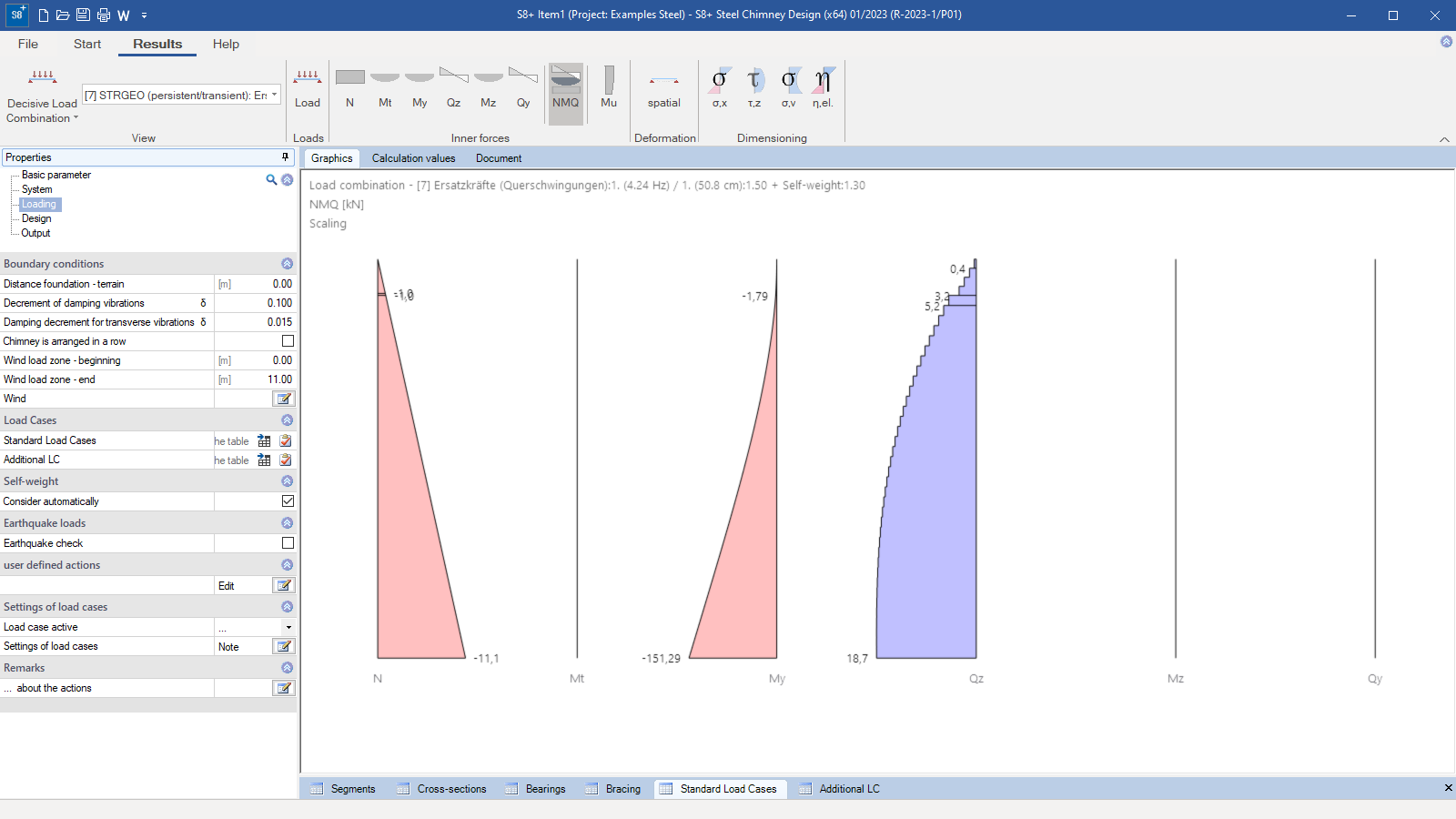 Courses of internal forces in the result view
 -
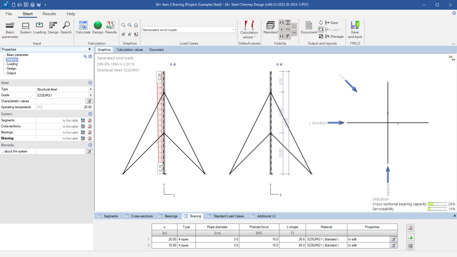 Bracing
 -
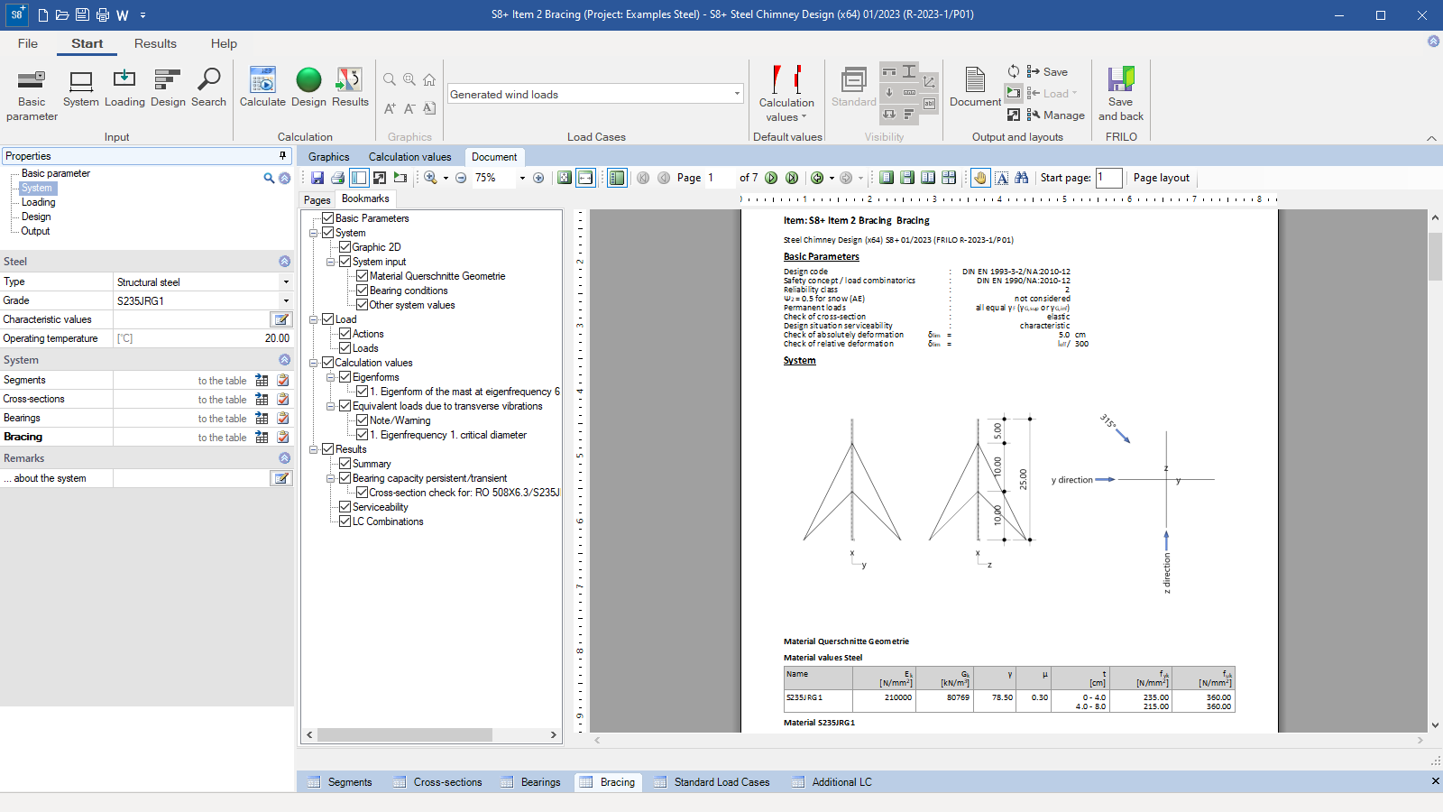 Output document
Steel Chimney Design
S8+
S8+ designs steel chimneys according to Eurocode 3, taking into account the regulations of the national appendix. The program calculates the internal forces and deformations according to the second-order theory of elasticity. The eigenfrequencies are determined, with which the structural safety, the operational strength and the serviceability are verified.
Discover now more programs from the section Steel!
SHOW MOREMaterial
- Structural steel: S235JRG1, S235JRG2, S235J2G3, S275 JR, S275J2G3, S355J2G3
- Structural steel weather resistant: S235 JRW, S355J2WP, S355J2G1W
- Structural steel fine grained: 1.0425,1.5415, 1.7335, 1.7380
- Stainless steel: 1.4301, 1.4541, 1.4571, 1.4404, 1.4435, 1.4539
- heat resistant steel: 1.4878, 1.4841, 1.4828
- user defined type
Structural system
System
- Input of several segments with different cross-sections and materials
Static Systems
- cantilevered chimneys clamped at the base
- cantilevered, arbitrarily supported at the base clamped or articulated chimneys
- braced chimneys with three or four cables (additional option S8-S required)
Cross sections
- Round tubes as standard profile
- Round tubes user defined
Detail points
- Base
- circular or annular,
- with/without rib,
- with/without ring stiffener
- Flange connection (internal/external)
- Flue opening
Bearings
- The support at the base can be defined as either rigid, articulated or elastic (enter a spring value).
- Additional bearings can be arranged along the chimney for each segment.
Bracing
Additional option S8-S required. Bracing of the system can be defined. There is a choice of three or four ropes.
Loads
- automatically generated wind loads depending on the selected location
- automatically generated equivalent loads from eddy-excited transverse vibrations
- automatically generated seismic loads
- automatic consideration of the self-weight of the profiles
- Additional, user-defined load cases can be entered (e.g. icing of the support tube, temperature loads, etc.)
Verifications in the ultimate limit state
The verifications in the ultimate limit state include:
- Verification of the load-bearing capacity of the cross-section taking local buckling failure into account (verification of the c/t limit values and classification into cross-section classes)
- Verification of the elastic cross-section resistance (verification of the equivalent stresses) according to EN 1993-1-1, Eq. 6.1
Verification in the serviceability limit state
The calculation is carried out with the design situation selected in the basic parameters:
- Verification of the absolute deformation. The proof of serviceability is carried out with the deformation difference to the undeformed system.
- Proof of relative deformation. The proof of serviceability is based on the deformation differences related to the effective lengths. The effective lengths are determined by the inflection points of the bend line
Earthquake
If required, the program carries out an earthquake verification. The seismic loads can be determined according to DIN 4149, 6.2.2. or DIN EN 1998-1 according to the simplified response spectrum method.
Detailed verifications
- Verification of the flange connection
- Verification of the base point
- Verification of flue opening
Additional option
Steel Chimney anchored by ropes S8-S
With the additional license S8-S the bracing of the system can be defined. The height of the bracing on the system and the number of ropes can be selected. There are three or four ropes to choose from. It is also possible to apply a pre-tensioning force to the guy ropes.
Document file formats
- Word
- Printer
Output
- pre defined brief output
- User-defined
Result graphs:
- Internal values: N, Mt, My, Qz, Mz, Qy
- Deformations: spatial
- Stresses: σ,x; τ,z; σ,v
- Utilization Eta: n,el
Import/Export options
Import:
- ASCII-Datei
- FRILO XML
Export
- Word
- FRILO XML
Structural safety verifications
- DIN EN 1993-1-1/NA
- DIN EN 1993-3-2:2010:12 /NA
Wind and snow loads
- DIN EN 1991-1-3/NA
- DIN EN 1991-1-4/NA
Fatigue
- DIN EN 1993-1-9/NA
Earthquake
- DIN 4149
- DIN EN 1998-1/NA
Support resources
News

Efficient design of steel chimneys and antenna masts as per Eurocode 3
With Release 2023-1, the software manufacturer FRILO has responded to the needs of structural engineers and launched programs for the design of Steel Chimneys (S8+) and Antenna Masts (ATB+).

FRILO Release 2023-1: The latest version saves time and contributes to climate efficiency
FRILO Software GmbH has successfully delivered the software version 2023-1. With the update, the vendor of innovative solutions for structural analysis and design launches four new PLUS programs – including DLT Continuous Beam.