
-
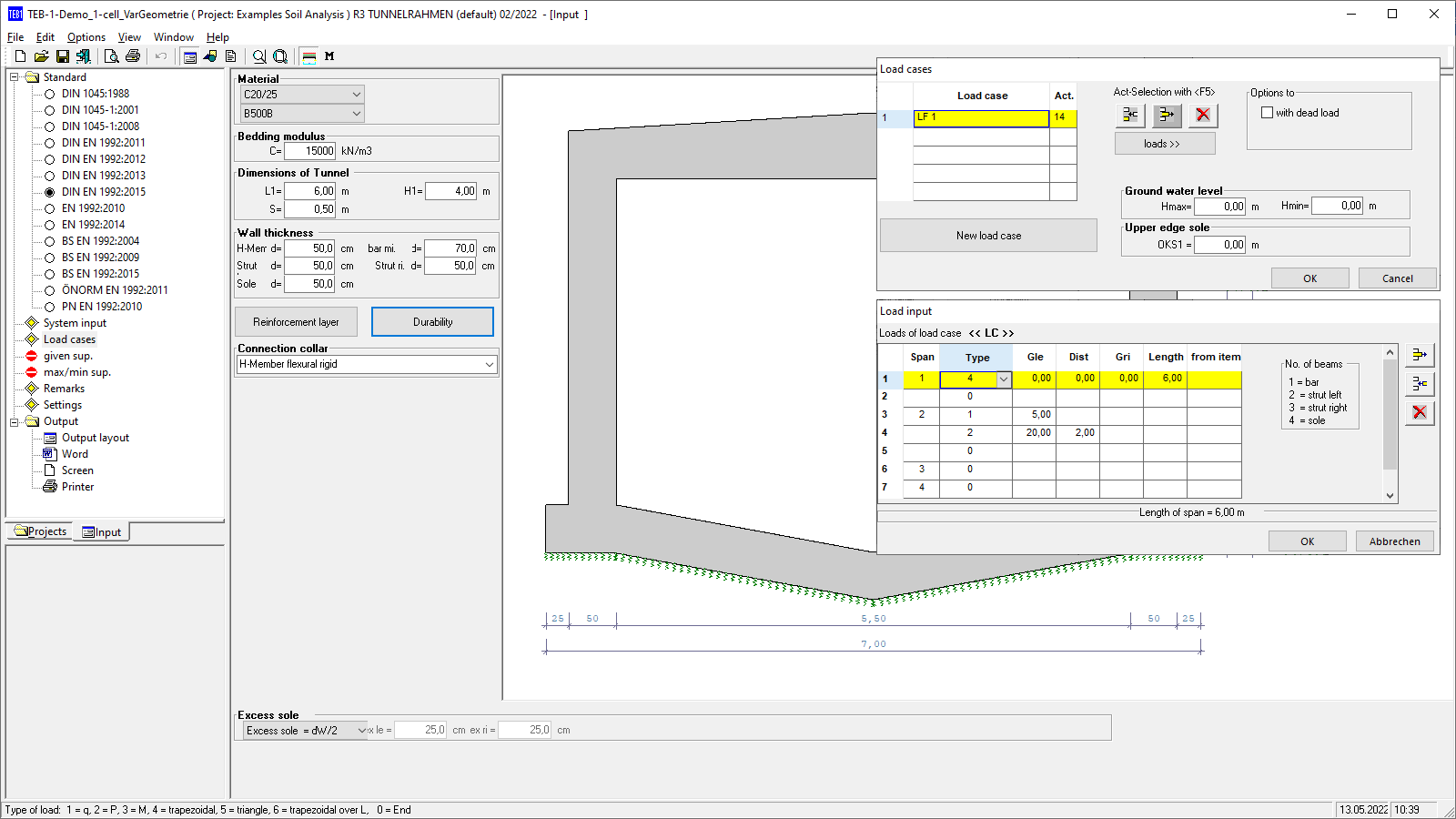 TEB-1 user interface
 -
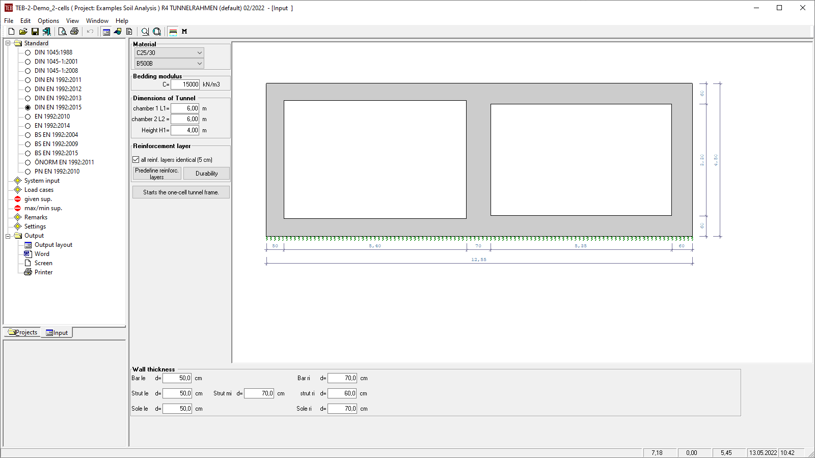 TEB-2 user interface
 -
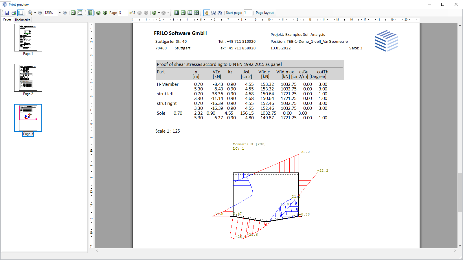 Output document, enveloping curve of the design moments
Tunnel Frame
TEB
The TEB program can be used to calculate rectangular single-cell (TEB-1) and twin-cell (TEB-2) frames with a continuously bedded base slab. The calculation is based on the displacement method and the subgrade reaction modulus method. The stiffness matrix is generated from the system values. Subsequently, displacement and torsion of the nodes are assessed and the internal forces and the soil pressure are calculated on this basis. The stiffness of the members is calculated for state I. The structural system is a sway system.
Discover now more programs from the section Foundation Engineering!
SHOW MOREMaterial
- Reinforced concrete with selectable concrete qualities and steel grades, depending on the selected standard
Structural system
Variant Single-cell Tunnel Frame (TEB-1)
- Optional arrangement of a camber S and/or a base projection on the left (bple) and right (bpri)
- Optionally, higher thickness in the middle of the horizontal member than at its ends
- Flexurally rigid or pinned connection of the horizontal member to the vertical members
- Optionally, also without horizontal member
- Different wall thicknesses for the horizontal member, the vertical members, and the base
- Any tunnel geometry (tunnel width L1, tunnel height H1)
Variant Twin-cell Tunnel Frame (TEB-2)
- Any tunnel geometry (tunnel width L1, width of the second chamber L2, tunnel height H1)
- Different wall thicknesses for the horizontal members, the vertical members, and the bases in both chambers
Any reinforcement layer in all individual members (vertical, horizontal and bases), internally and externally
Durability dialog to specify exposure classes
Soil:
- The elastic bedding and/or the soil properties are represented by specifying a subgrade reaction modulus
Groundwater:
- For the calculation of the safety against buoyancy, the maximum and minimum groundwater level can be specified for single-cell frames.
Loads
- Any types of loads applying to all individual members:
- Uniformly distributed load over the entire span length
- Concentrated load at a defined distance
- Concentrated moment load at a defined distance
- Trapezoidal load with specific length and different load coordinates on the left and right
- Trapezoidal load over the entire span length
- Triangular load over the entire span length
- Self-weight can be applied automatically
- Free assignment of loads to load cases and to a type of action as per EC 0.
Superposition:
- Automatic min/max superposition of permanent and freely selectable variable actions
- Any pre-set user-defined superpositions
Settings
- Durability verification via exposure classes
- Consideration of a minimum reinforcement quantity
- Partial safeties can be applied
Reinforced concrete design
- Bending design
- Shear design
Document file formats
- Word
- Printer
General
- System data represented graphically and in tables
- Decisive concrete volume and total weight of the construction, if applicable
- Cross-sectional properties A and I for all individual members
- Internal forces in the buckling points of the individual members M, N, Q per load case and for each design situation
- Displacements of the base slab and soil compression per load case and for each design situation
Reinforced concrete design
- Bending design with required As in tables
- Shear design with required As,w in tables
- Graphical representation of the moment lines in all members
Transfer options
Export from TEB-2 to TEB-1 for single-cell design
Reinforced concrete
- EN 1992
- DIN EN 1992
- ÖNORM EN 1992
- PN EN 1992
- BS EN 1992
- DIN 1045
Support resources
News
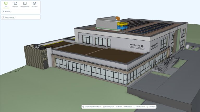
Role model baues + partner – Multi-layered and progressive BIM planning
BIM is not software, but a planning method: this is demonstrated by the ultra-modern multifunctional building that will be built on the Gottschall + Sohn KG company premises.

“FRILO means precise and efficient work to me”
By switching to the FRILO Suite, the engineering office BILGER INGENIEURE decided to rely on the FRILO subscription model. The numerous advantages convinced the long-standing customer.