
-
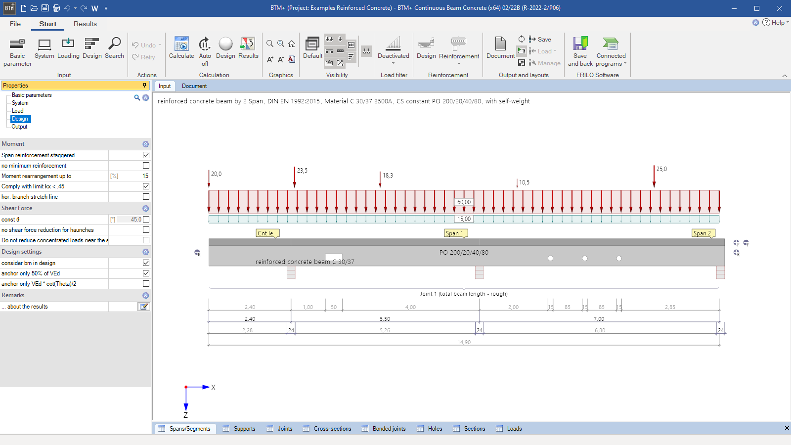 BTM+ user interface on the design tab
 -
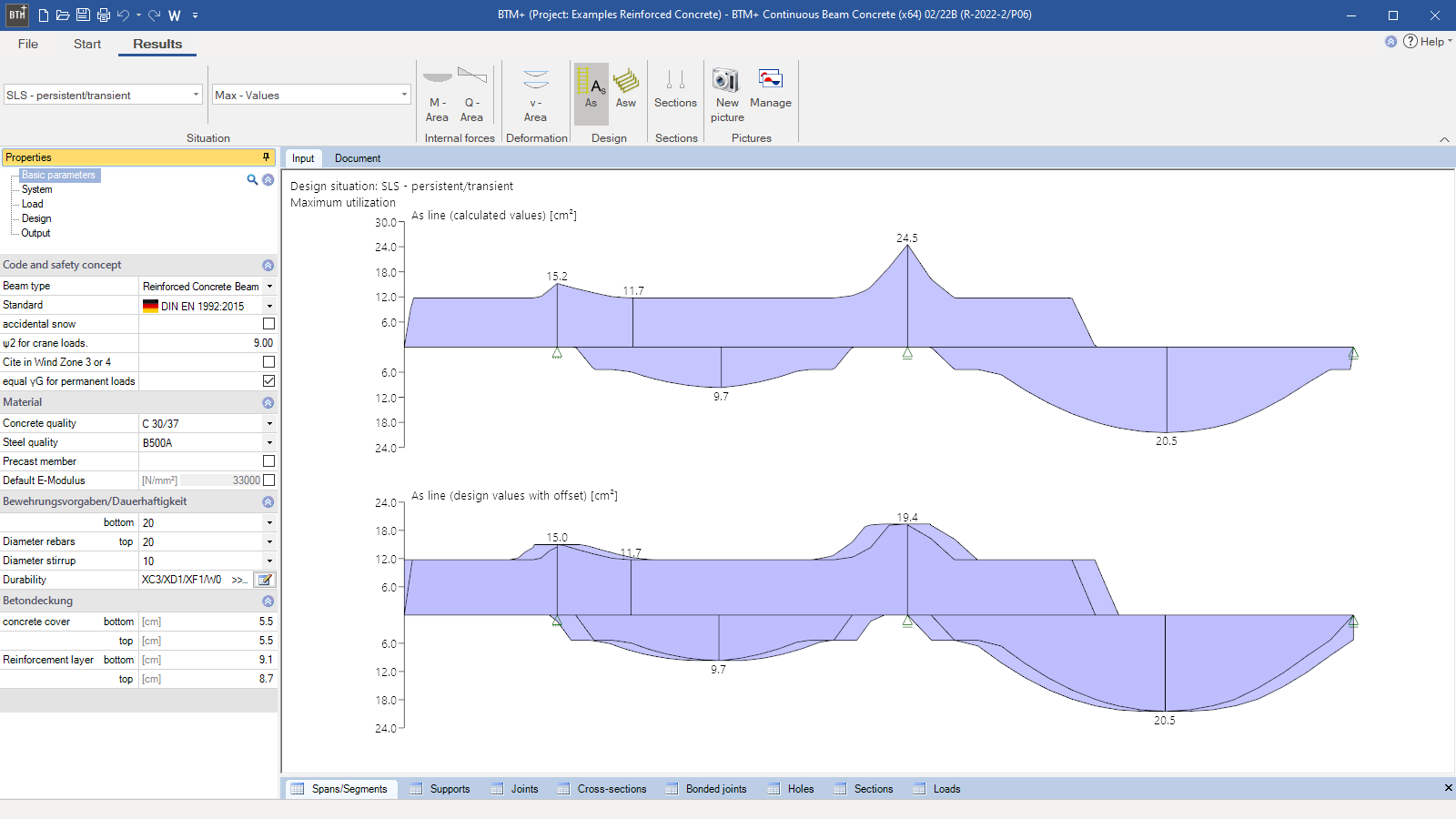 Graphical representation of the design results
 -
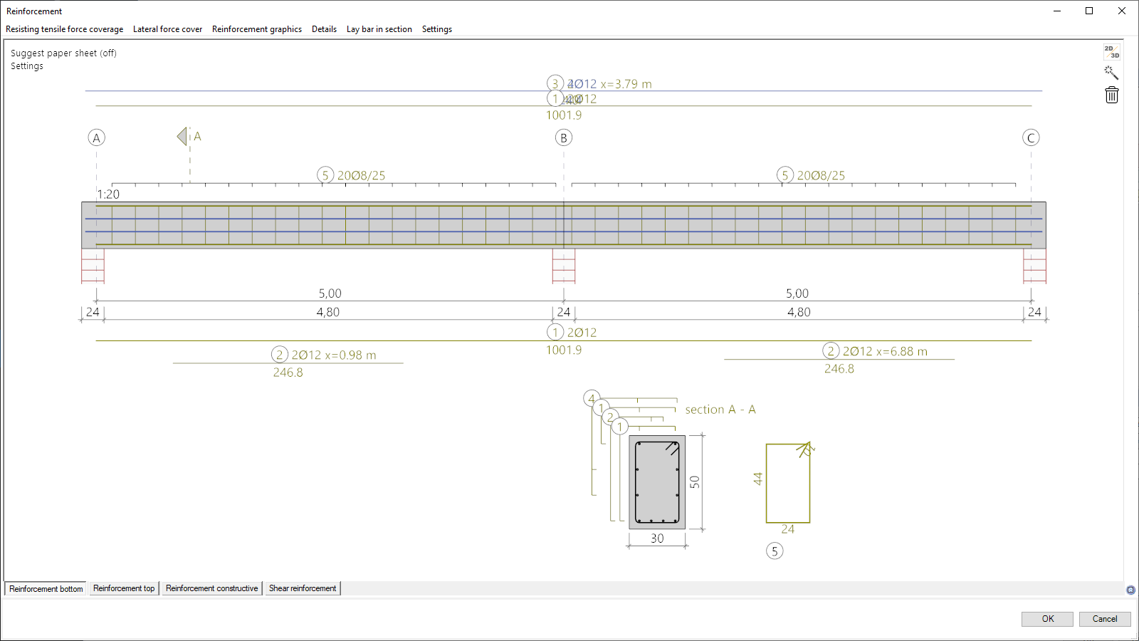 Reinforcement dialog as Add-on
 -
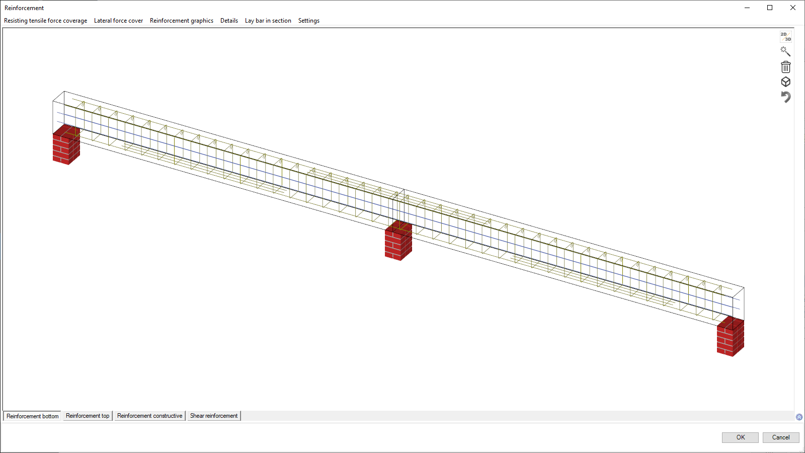 3-d view of the reinforcement
 -
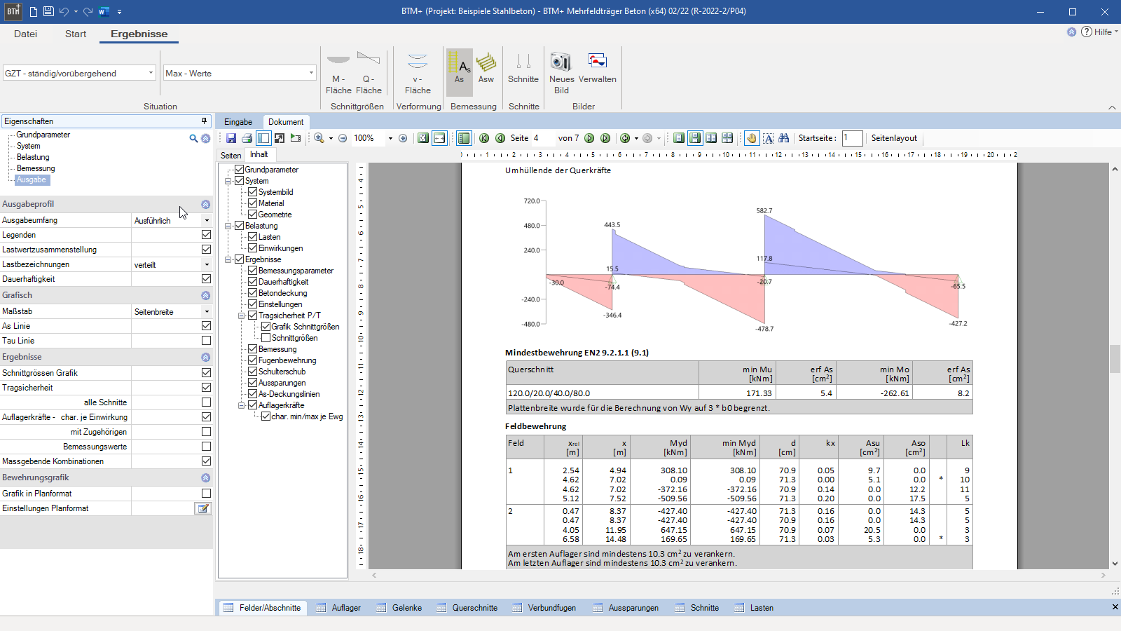 Output document with graphic
Continuous Beam Reinforced Concrete
BTM+
DLT+The BTM+ program is used to calculate single-span and multi-span beams as well as T-beams and slabs made of reinforced concrete. A cantilever beam is selectable as a special case. Cross-sections can be defined with a haunch, with joints or with a cross-sectional discontinuity. In addition to performing all required verifications, the program offers detailed setting options for the design. Interactive options for a complex reinforcement layout are available via Add-on.
Discover now more programs from the section Reinforced Concrete!
SHOW MOREMaterial
- Concrete of all strength classes (C 12/15 to C 100/115) specified by the standard
- Lightweight concrete of the strength classes LC 12/13 to LC 80/88
- Consideration of concrete as a pre-cast component
- Free specification of the modulus of elasticity
- Durability and creep factor can be defined in accordance with DIN EN 1992-1-1/NA/A1
Structural system
- Single-span or multi-span beam with or without cantilevers
- Different cross-sections for each span or section
- Concrete cover on top/bottom based on the durability requirements
- Any type of haunched beam
- Definition of pinned joints in the system
- Lateral restraints are adjustable
- Definition of composite joints on T-beams
- Consideration of block-outs in the beam
- Various support systems are available (masonry, concrete, direct support, indirect support etc.)
Loads
- Vertical loads resulting from linear, concentrated, moment, triangular, and trapezoidal loads
- Self-weight can be considered automatically.
- Each load can be defined individually for the spans
- Consideration of a beam spacing with automatic conversion of area loads
- Definition of concurrency and alternative groups
- User-defined actions with freely selectable partial safety factors
- Import of loads from the LAST+ program
Cross-section
- Beam (rectangular cross-section)
- T-beam (slab on top and/or on bottom)
- Reinforced concrete slabs (pre-set as stripes of 1.00 m width)
- Free selection of dimensions
- Freely definable sections for each span
Structural safety
The design is performed in accordance with EN 1992-1-1, section 6. The ultimate limit state design for shear forces is carried out in accordance with Eurocode EN 1992-1-1 section 6.2 and the decisive shear force is determined in accordance with section 6.2.1. The span reinforcement is calculated for the maximum midspan moments. If the maximum midspan moment is negative, the required upper reinforcement is put out in addition. The permissible moment redistribution for high-ductility steel is limited in accordance with EN 1992-1-1 section 5.5. If standard concrete and high-ductile reinforcing steel have been selected, a simplified verification of the plastic rotation capacity is performed.
In addition, the effective slab width for T-beams is determined automatically and a verification of the connection of the compression chord (shear joint analysis) is performed. For slabs and T-beams, the shear joint is verified. You can define round and rectangular block-outs for reinforced concrete beams. If concentrated loads apply in the area of the block-out, the user must check the load distribution manually with slender remaining cross-sections (load-bearing effect of the beam). The verification is performed according to Booklet 399 of the German Committee for Reinforced Concrete DAfStb. The same verification is performed for round and rectangular block-outs.
Serviceability
In addition to the deformation calculation in state I with 1.0 times loads and gross concrete cross-section, the deformations in state I and II can be calculated according to EN 1992-1-1. In this case, the calculation is performed with quasi-permanent load combination and taking into account the reinforcement actually present. The influence of creep and shrinkage is taken into account via the defined parameters creep coefficient and shrinkage dimension. The resulting deflection values are output separately.
The verification for crack width limitation is performed according to EN 1992-1-1 7.3 for the quasi-permanent load combination. In addition to the crack width limitation (limit diameter), the stress verification is considered. The requirements from durability are taken into account.
Additional options
Reinforcement Layout BTM-BEW:
The additional option BTM-BEW can be used to generate a reinforcement graphic via an interactive input window. Based on the options set in the program, a fully automatic reinforcement is suggested. This can be adapted and supplemented extensively and in detail. All reinforcement rules are checked. The utilization of each reinforcement item is displayed graphically. It is also possible to display the reinforcement in a 3D view at any time. Opening can be adjusted in detail. The generated reinforcement graphic can be output to any DIN format with or without a plan header.
Biaxial-Bending BTM-2:
A biaxial design is available with the optional additional license BTM-2.
File formats
- Word
- Printer
Output
- Brief
- Extensive
- Without design
- User-defined
Data transfer options
- Single-span Steel Column STS+ (support reactions)
- Timber Column HO1+ (support reactions)
- Reinforced Concrete Column B5+ (support reactions)
- Continuous Beam Steel STM+ (entire system)
- Continuous Beam Timber HTM+ (entire system)
- Framework RSX (entire system)
Load import
- Load Compilation LAST+
Import options
- FRILO XML
- ASCII-file
Export options
- Word
- FRILO XML
Reinforced concrete construction
- DIN EN 1992
- ÖNORM EN 1992
- NTC EN 1992
- BS EN 1992
- PN EN 1992
- EN 1992
News
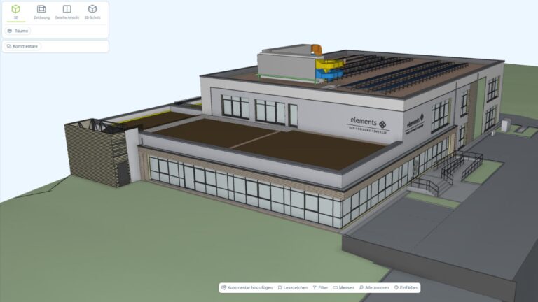
Role model baues + partner – Multi-layered and progressive BIM planning
BIM is not software, but a planning method: this is demonstrated by the ultra-modern multifunctional building that will be built on the Gottschall + Sohn KG company premises.

“FRILO means precise and efficient work to me”
By switching to the FRILO Suite, the engineering office BILGER INGENIEURE decided to rely on the FRILO subscription model. The numerous advantages convinced the long-standing customer.